Fixing an Analog Thermocouple Gauge

Every fusor and fusion system seems to need a vacuum. This area is for detailed discussion of vacuum systems, materials, gauging, etc. related to fusor or fusion research.
Post Reply
Charles Vorbach
Posts: 45
Joined: Tue Oct 14, 2014 6:39 pm
Real name: Charles Vorbach

Fixing an Analog Thermocouple Gauge

Post by Charles Vorbach »

I got a broken Duniway TCG-531 tube thermocouple gauge. I think should be relatively simple to fix, but I am having trouble understanding the circuit diagram.
Meter Diagram.png
From the 12th page of the manual at https://www.duniway.com/images/_pg/manu ... 31-06M.pdf.

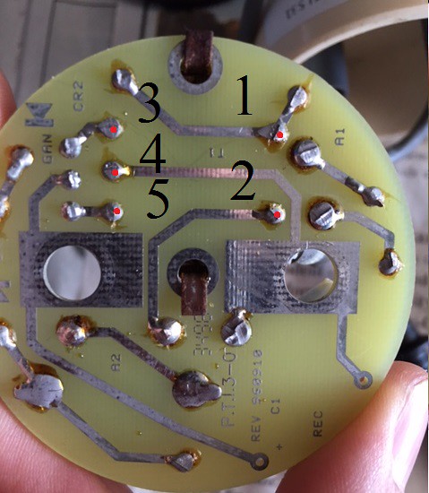
This is what I think is going on, but correct me if I am wrong. Current is supplied by an outlet, the voltage is divided by the variable resistor R2 and R1. Then the voltage is stepped down to supply the heater inside the gauge tube. A meter reads between 0 and 11 milliVolts between one end of the thermocouple and the center tap of the transformer. The Thermistor has something to do with making the reading more accurate.

I have no idea what the diodes are for or the capacitor. The diodes seem to do nothing as they are in opposite directions, but they probably have some function I don't understand. I also am foggy on the placement of the meter and why there are only 3 connections.

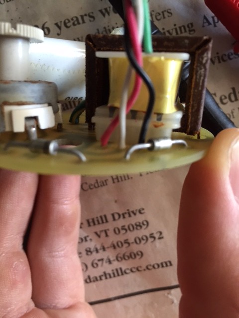
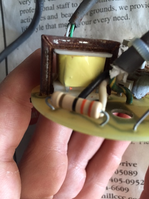
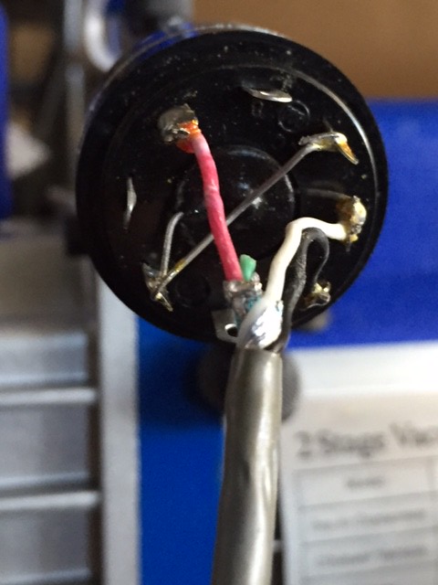
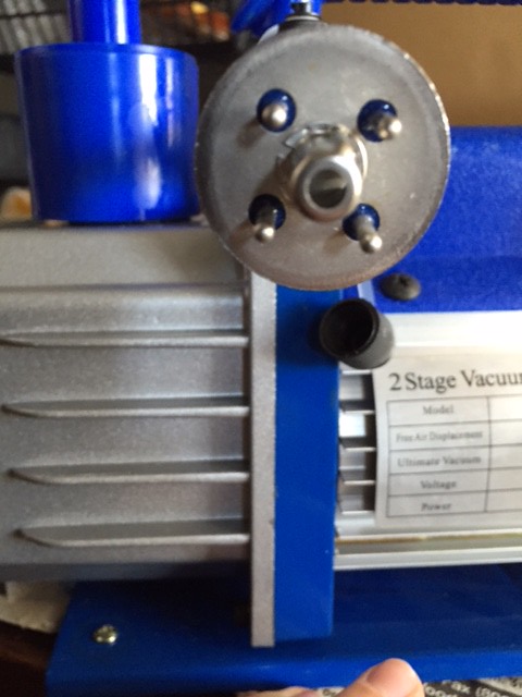
I have pictures of the inside of the gauge below. I tested the meter and it works. The gauge is dated 4/7/15 but, everything inside is rusted so it must have been in a corrosive environment.
circuit front.jpg
circuit back.jpg
circuit parts.jpeg
meter circuit.jpg
meter.jpg
gauge info.jpg
The cable with three wires leads to the plug and the cable with 4 wires leads to the gauge tube. The clipped green wire seems suspicious to me, but there isn't anywhere it obviously goes.

Resistors R1 and R2 work, reading 33 ohms and 0 to 175 ohms respectively. Opposite sides of the transformer read around 100 kiliohms. When plugged in the meter's needle moves from OFF to ATM, meaning it reads at some voltage but doesn't move from there.

I would really appreciate any advice figuring out the circuit or what I could do to fix it.
User avatar
Richard Hull
Moderator
Posts: 15023
Joined: Fri Jun 15, 2001 9:44 am
Real name: Richard Hull

Re: Fixing an Analog Thermocouple Gauge

Post by Richard Hull »

Sounds like the transformer is open. 100k ohms is way too high a resistance.

Richard Hull
Progress may have been a good thing once, but it just went on too long. - Yogi Berra
Fusion is the energy of the future....and it always will be
The more complex the idea put forward by the poor amateur, the more likely it will never see embodiment
User avatar
Bob Reite
Posts: 579
Joined: Sun Aug 25, 2013 9:03 pm
Real name: Bob Reite
Location: Wilkes Barre/Scranton area

Re: Fixing an Analog Thermocouple Gauge

Post by Bob Reite »

I thought that he meant leakage between primary and secondary with that kind of reading.
The more reactive the materials, the more spectacular the failures.
The testing isn't over until the prototype is destroyed.
User avatar
Richard Hull
Moderator
Posts: 15023
Joined: Fri Jun 15, 2001 9:44 am
Real name: Richard Hull

Re: Fixing an Analog Thermocouple Gauge

Post by Richard Hull »

If it was leakage, he needs to measure each sides coils and report them, (tube unplugged of course). Also he needs to meter his tube's heater and internal thermistor. More data.

Richard Hull
Progress may have been a good thing once, but it just went on too long. - Yogi Berra
Fusion is the energy of the future....and it always will be
The more complex the idea put forward by the poor amateur, the more likely it will never see embodiment
Charles Vorbach
Posts: 45
Joined: Tue Oct 14, 2014 6:39 pm
Real name: Charles Vorbach

Re: Fixing an Analog Thermocouple Gauge

Post by Charles Vorbach »

Ok, the transformer has 5 terminals. I labeled them below. There are 41.9 ohms between 1 and 2. Terminals on different coils, 1 and 3, 1 and 4, 1 and 5, 2 and 3, 2 and 4, and 2 and 5, all read open loop. There are .5 ohms between 3 and 4 and between 4 and 5. There is 1 ohm between 3 and 5.

Image
Image
Image

That seems to suggest the transformer isn't open or leaking. I am sorry for the incorrect resistance value before. I don't know how I got it.

I opened up the octal socket. At room temperature, the thermistor reads 1.9 ohms. I got a pin-out from Duniway that says the top right and bottom right are for the heater, while the top and bottom left are for the thermocouple. The fifth pin with the white wire isn't connected to the tube.

Image
Image

There are 1.7 ohms of resistance between each pin without the octal socket. That could be the problem. Maybe the heater is shorted? There is an open loop between each pin and the metal tube body.

With the octal socket on there is only 1.2 ohm between each of the four pins - probably because of the better connection.

Is there any more data I should provide?
Rex Allers
Posts: 574
Joined: Sun Dec 30, 2012 3:39 am
Real name:
Location: San Jose CA

Re: Fixing an Analog Thermocouple Gauge

Post by Rex Allers »

I don't have a lot of experience and thought someone else might chime in, but let me ask one thing.

You said, "When plugged in the meter's needle moves from OFF to ATM, meaning it reads at some voltage but doesn't move from there."

That sounds like proper operation. Have you connected it to a vacuum and there is no change in reading? Do you mean doesn't move from there is after vacuum is applied? You never actually stated that.

All your measurements seem reasonable to me. You were puzzled by the diodes. From the manual they are 6.8 V zeners, not simple diodes. I guess they limit the V across the transformer primary to a very low voltage swing. The capacitor lets a small amount of AC through but limits it. The only thing odd is that I don't see the thermistor to A & B shown in the schematic even though it seems to be a 531 gauge.

I think 1 or 2 ohms between pins on the tube is not unreasonable.

But I wouldn't worry about the circuit for now. Please clarify that you have applied a good vacuum to the tube and the meter doesn't move from ATM counterclockwise to one of the numbers. So far I'm not sure it isn't working correctly.
Rex Allers
Charles Vorbach
Posts: 45
Joined: Tue Oct 14, 2014 6:39 pm
Real name: Charles Vorbach

Re: Fixing an Analog Thermocouple Gauge

Post by Charles Vorbach »

Yes, I apologize if I wasn't clear. I pulled a vacuum on the tube with a two stage HVAC pump. The needle should move from indicating ATM to some lower pressure. However it does not.

In case the pump wasn't working, I also tried this with a two stage Edwards pump. The result was the same. The needle sat at ATM.
Bruce Meagher
Posts: 148
Joined: Thu May 12, 2011 11:25 pm
Real name: Bruce Meagher
Location: San Diego

Re: Fixing an Analog Thermocouple Gauge

Post by Bruce Meagher »

Are you really sure it's your gauge or controller? In my experience pulling the needle off "ATM" on that gauge actually requires a (relatively) decent vacuum. When I started, I was surprised how easy a single improper seal could create a giant leak.

Maybe post a pick of your vacuum pump connections. How are you connecting the thermocouple to the vacuum pump's input port, and what are you using to seal each connection.

Here's a post of a similar issue viewtopic.php?f=10&t=9432
Rex Allers
Posts: 574
Joined: Sun Dec 30, 2012 3:39 am
Real name:
Location: San Jose CA

Re: Fixing an Analog Thermocouple Gauge

Post by Rex Allers »

Charles, I agree with Bruce that you may have a vacuum issue, rather than a meter issue. Everything you have posted about the meter and tube sounds good.

I have a Varian 0531 tube here, but no meter, and I have never tried to use it. Your post caused me to try to understand how the meter should work. It's a pretty simple circuit and now I think I have figured out the tube internals and understand it.

First, I edited your picture of the base and added pin numbers. At first I didn't see the thermistor, but now I do and I made its leads orange to make them easier to see in the picture.

I found a doc on the Hastings site that is supposed to be the pin-out for a 531 but it doesn't make sense. I think it is really for a DV-6M tube.

Looking into the end of my 531 with a microscope I can see two wires that cross and are probably welded together where they intersect. I made a drawing of that with the two wires in red and green. I don't know what metals they are but to form a thermocouple they have to be different.

To verify this I connected a meter on my lowest 200 mV scale, across two of the pins (3 & 5). I stuck the end of the tube in the stream of a hot air gun so some of the hot air was circulating into the tube, heating the wires inside. After several seconds I started seeing voltage out. The voltages I saw were very low -- about .2 to .5 millivolts with hot air, so I think the wires are hotter in operation.

I have labeled the pins with (+) and (-) to show the polarity of this thermocouple output voltage. Between either of the (+) pins and (-) pins I see a voltage, but there is no output between the two (+) or the two (-). So I think I have the internals of the 531 tube figured out.

This makes sense for the meter connections too. The heater voltage from the transformer is between the red and black wires that go to pins 7 and 3, so the green wire in my drawing is heated. For the output signal this wire is referenced to ground by the center tap of the transformer. On the socket, pins 1 and 5 are connected together so the two thermocouple (+) outputs are connected in parallel.

This combined output of pins 1 and 5 goes back to drive the meter through the white wire, but first it flows through the thermistor. This must be to compensate for signal changes due to ambient temperature changes.

It wasn't totally clear in your messages but I think you measured the resistance across the thermistor with no tube plugged in. As long as this is low (less than a few ohms) the signal should get back OK.

I redrew the meter schematic a bit to make it more clear that the thermistor is in the tube socket and to add the pins for the 531 tube. The 531 has no pin 2, so the socket pin 2 is just used as a floating connection point for the thermistor and white wire.

So I think everything sounds OK in your meter and tube. The 1 to 2 ohms between any of the four tube pins shows that the two wires inside are connected and welded together. If you want, you could do my heat gun measurement on just the tube to verify the thermocouples actually make voltage, but I expect they will.

So it seems to me that we are back to everything is OK except the vacuum is not affecting the temperature of the wires inside. That is most likely a vacuum issue.

At least you got me to really understanding how this meter and the 531 tube work. It is my understanding that the arrangements of wires and junctions inside other tubes is different. The 531 tube construction is very simple, it seems.
Attachments
TCG-531 redraw.png
531 sensor theory.png
DV-531 pins.jpg
531 socket num.jpg
Rex Allers
Charles Vorbach
Posts: 45
Joined: Tue Oct 14, 2014 6:39 pm
Real name: Charles Vorbach

Re: Fixing an Analog Thermocouple Gauge

Post by Charles Vorbach »

Thank you so much for all your help. I really appreciate your patience in helping to find the problem. I get the circuit now.

I did an extended pump down today. Here is my connection to the pump.
image.jpg
It is a short pvc tubing connection between the pump and gauge tube. I sealed it with epoxy and allowed it to cure for ~5 hours. I know PVC out gases a lot but I thought it would be fine for a short connection.

I turned on the pump and gauge. The needle sat at ATM for about 15 minutes before suddenly moving to 200 microns. The sound of the pump noticibly changed. After a few seconds the needle fell back to ATM. After moving back and forth several times it settled at 200 microns. Over the course of an hour, the needle eventually reached 180 microns.
image.jpg
I shut off the pump, then started it up again. The needle rose to 200 microns immediately. I guess that means water vapor or something was outgassing.

I fiddled with the calibration, but it didn't change the reading at all. My pump is new, but could be dysfunctional. I am going to try a long pump down with another pump and see what the gauge reads.
John Futter
Posts: 1850
Joined: Wed Apr 21, 2004 10:29 pm
Real name: John Futter
Contact:

Re: Fixing an Analog Thermocouple Gauge

Post by John Futter »

Charles
your connections are dysfunctional
you must use the proper barb type connections and jubilee clips for the gauge to pump. Hot melt glue is not recommended.

With a big leak you will quickly poison your pump oil with water from the water content of normal air. This will require quite some time with the pump in gas ballast to remove the water from the oil. Your pump sitting at around 200 microns is the clue to water contamination
Kevin OConnor
Posts: 1
Joined: Sat Dec 19, 2015 9:51 am
Real name: Kevin OConnor

Re: Fixing an Analog Thermocouple Gauge

Post by Kevin OConnor »

Realizing this is a dated thread.....
I have tried several of these so called vac pumps from China.
None of them could reach anywhere near the nameplate vacuum!
The two I have occasionally drop below 50mu when cold started, but stabilize
at 200-400mu.
I bought a old Welch 1405 with maple syrup for oil. After a few oil changes, it
got the same system to 8-10mu in 2min.

Those little pumps are inticingly cheep, but a quality vacuum is not!
Post Reply

Return to “Vacuum Technology (& FAQs)”