All excellent details and thanks for cleaning up and analyzing the drawing Mr. Allers! I may end up now modifying the circuit I just installed but not a big deal either way. So, the photo's I have may change (a good bit!) If a doubler is required; if so, that I can do as well. I am fairly certain you are correct and the x-former is rated for 15 kV or so. I will simply test it using my existing setup since this design provides negative and positive 15 kV on the bridge (assuming the diodes survive!)
The first photo the standard bridge is shown (and the x-former.) The negative output of the bridge is connected to a HV lead out; the positive side of the bridge has not, as yet, been connected to anything. I did not want to 'float' the case until I have a second, physically separate ground wire for the case (to a water ground) and not depend on the wall outlet plug alone. The core is grounded (via a wire to the case) so even through it is mounted on wood, that isn't an issue.
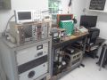
The second photo is the nice case I have; the two digital meters can be used for voltage and current once I install appropriate resistors. The varic is beefy and can handle the load easily (it is rated for 15 amps and the x-former only for 10 amps.) I have a 10 amp fuse in line with the "hot" side of the x-former input power.
The last photo shows the entire internal system (less oil on the diodes.) The main output resistor (50 kilo-ohms) is under oil for cooling - the diodes really don't need oil if the max voltage is 15 kV or so. The "positive" side of the x-former has a 100 ohm resistor to protect the x-former from any surge to the bridge.
I will carefully review what needs to be done after I test the x-formers voltage in the bridge (my HV probe only reads positive voltages ... .)
All major parts are modular and can be removed/changed as needed without causing issues for the overall setup since the wires have dis-connections built in.
The diodes are cheap and are rated to 20 kV but have been proven only to 15 kV; so I (hope!) they can stand the 32 kV as doubled sets (if it can really do that ... .)
Took only a few hours to put this all together but between having an available case, some spare diodes/electrical parts/extra HV wire and more junk parts on hand, managed to do it today. Hope the results aren't explosive for the diodes. The resistor I would think will provide protection to the x-former if the diodes fail.
High voltage Fusor grade x-former score (Temporary)
-
Dennis P Brown
- Posts: 3189
- Joined: Sun May 20, 2012 10:46 am
- Real name: Dennis Brown
-
Rich Feldman

- Posts: 1471
- Joined: Mon Dec 21, 2009 6:59 pm
- Real name: Rich Feldman
- Location: Santa Clara County, CA, USA
Re: High voltage Fusor grade x-former score (Temporary)
Rex called it right, about voltage doubler in original schematic, and questioning the secondary voltage of transformer itself.
Thank you for figuring out how to bridge the gap between right scan, say abcdefghij, and left scan, abcdeghifj. The mismatched vertical spacing had deterred me on pass 1. Duh!
Here I have re-drawn the circuit for clarity, assuming that the wire from J103 goes to an external mA meter.That ASCII rendering was adapted today from one I drew a long time ago, for another forum.
The configuration might be called a "symmetrical" voltage doubler. Both ends of the secondary are hot, but one is hotter.
You can make this doubler functional even if you have only one HV capacitor.
All three (?) of my high-frequency XRT's have multiple secondary windings, for multiple instances of this kind of doubler in series.
Thank you for figuring out how to bridge the gap between right scan, say abcdefghij, and left scan, abcdeghifj. The mismatched vertical spacing had deterred me on pass 1. Duh!
Here I have re-drawn the circuit for clarity, assuming that the wire from J103 goes to an external mA meter.
Code: Select all
+-(mA)--|<----+--|<--+--HVout
|       D1    |  D2  |
|          coil      |
|    C2    |    C1   |
+----||----+----||---+
|
GroundThe configuration might be called a "symmetrical" voltage doubler. Both ends of the secondary are hot, but one is hotter.
You can make this doubler functional even if you have only one HV capacitor.
All three (?) of my high-frequency XRT's have multiple secondary windings, for multiple instances of this kind of doubler in series.
All models are wrong; some models are useful. -- George Box
-
Dennis P Brown
- Posts: 3189
- Joined: Sun May 20, 2012 10:46 am
- Real name: Dennis Brown
Re: High voltage Fusor grade x-former score (Temporary)
The x-former does in fact produce 32 kV without any doubling; direct measure from the high side of the diode bridge (negative voltage) was just over 30 kV with loses from the exposed wires (a lot of crackling ... I need to reinstall the exposed hot lead back onto the fusor.) It was tricky to set up my voltmeter but have done that in the past without issue - the meter is calibrated. And yes, the diode bridge was grounded.
Since the original device had massive diodes (not sure what they are made of) but no caps that were of any significant size leads me to think that 1) that it is unlikely that the system doubled voltage since the original voltmeter scale didn't go above 35 kV or maybe 2) that drawing might not be exactly correct even through a lot of the stuff in it matches exactly to the drawing. Pity the original system doesn't work or I could have just used that and seen what/how it operates - through rather primitive (lol - but I bet very well done because I suspect that those huge and strange looking diodes make the modern semi-conductor ones look like the weak under rated units I am using.)
Considering the x-former size I have little doubt that it can handle 25 milli-amps but I will test that under vacuum (a few microns) in the original fusor (currently down due to its glass window having cracked; I sub a plastic one that allows 10-6 torr operation but hardly proper for a real fusor test with deuterium.) Until the new port window arrives, I will run tests at a few microns in the fusor using trace air to get a current meter to operate either directly (at the fusor and isolated so it can handle the full voltage) or with resistors using one of the digital displays. A voltmeter isn't really needed since the variac scale tracks perfectly with voltage (33% = 10 kV; 66% = 20 kV and 100% = 30 kV) but that is an easy one to install so I may just get the digital display for that working.
Playing with this new power supply and the fusor unit should bide me over until fall when humidity will drop enough so my Van de Graaff can be fired up and tested; even with a de-humidifier the room is just too humid to even consider a run. Until then I can try for some neutrons using this fusor; at least until I get the deuterium accelerator to operate (if only.)
I hope the 25 kV+ power supply can achieved its rated power and deliver 15 - 25 ma in the 20 kV+ range and this will provide me with enough neutrons to 1) confirm this occurrence and 2) try to operate my original experiment that was designed for the accelerator. Of course, this assumes I have no issues going forward.
So, to protect the x-former the secondary of the unit is first fed through a 200 ohm, 50 watt resistor (incorrectly said 100 ohm in the first post) before the bridge (on the positive side of the bridge where the ground wire is located); in the photo that bridge output lead was just floating (wire with connector hanging in the air) and hadn't as yet been connected to a ground. That was, of course, fixed before I fired the unit up. Floating a bridge is a sure way to burn out a x-former!) And on the negative side of the bridge that output runs through a 50 kilo-ohm, 100 watt resistor in oil that, in turn, then goes to the fusor. I'd think with the core grounded and these resistors the loads will not hurt the x-former. Also, even if the diodes fail, the 200 ohm resistor on the secondary and the 10 amp fuse (rating as called for in the spec's) for the primary should protect the x-former during any such run away condition. Any other protections for the x-former that I am overlooking? (aside; any one know why the core of a x-former needs to be grounded, over and above if a wire shorts to it the core doesn't reach those voltages.)
I will not use any caps as per everyone's advice. As a side issue, I didn't realize that the bridge does double the frequency from 60 Hz to 120 Hz. So, thanks Richard for pointing that out - obvious to many but not to me. I guess in hindsight I should have realized this fact but never thought of that ... .
I am not ready to sink the x-former in oil; it operates well in air and I am a bit worried oil might attack/weaken the x-former wrapping's; the owner wasn't real thrilled with that approach either when I mentioned it as a possible way to protect the unit ... .
I will top off the oil for the diode bridge system and resistors (aside. I will use synthetic oil since a paper I read proved this offers as good and even slightly better performance for HV systems compared to standard oils) and then I will close up the PS housing (the cabinet does need a better fan - it is aimed at the x-former.)
I will redesign my fusor with a current meter and maybe a voltmeter. I should be able to start tests this coming weekend on current loading/voltage for 5 microns (an arbitrary vacuum but one that is in the range of interest for fusion.) The main objective being to confirm current loading performance of the x-former; and secondarily, designing a good current meter system for the fusor (an important longer range goal.) Also, allow me to better develop a feel for the current/voltage/loading on my chamber. I do need a new cathode so, after the window comes in that will be my first project before trying some fusion. I will be careful of x-ray issues.
I will mothball my 40 kV supply (negative voltage output; works nicely and for under $100 (my std max price for any high end item - lol) I couldn't resist grabbing it when it was available. It is a Glassman unit.) But since it was good only up to 10 milliamps (with extra forced air cooling) I realized that there was no way it could reach even that level in the 20 kV range so this was just a backup PS. Maybe test that unit in a future day (and really push it to see exactly what it can do) when I finish my major experiments with this x-former and after I return this x-former (and had better be working!)
-
Dennis P Brown
- Posts: 3189
- Joined: Sun May 20, 2012 10:46 am
- Real name: Dennis Brown
Re: High voltage Fusor grade x-former score (Temporary)
Now that the system/x-former can provide negative 30 kV (and hopefully, I will determine if the 20 - 30 ma range is ok), I've ordered the new glass circular view window/electrode feed thru for the fusor (8.5 inches by 5/8 inches thick.) Also, topped off the oil for the bridge and replaced the missing front panel and re-installed the top on the power supply cabinet. Still have to address the issues in the previous post but that is for the future.
Decided I will add a deuterium low pressure fill tank to the fusor and install its own leak valve; in this manner I can operate the fusor away from the accelerator (currently a fill line connects the two units.)
As such, decided to move the deuterium fill station off the deuterium accelerator as well and make a separate, independent enclosure. The accelerator main hemisphere has it own deuterium mini-tank/needle valve.
I will use this deuterium fill station to fill either of my two low pressure deuterium holding tanks (each to about atm after a high vac pump out) from the high pressure deuterium lecture bottle. This will simplify operations of either system and allow them to be separate a good deal helping me work safer - too many high voltage systems in my research lab room in the house - the Van de Graaf is very large and the accelerator is a complete bench. Add my work benches and now a fusor with that rather large power supply and crowding is getting bad ... life as a home experimentalist ... the significant other wasn't happy when I took the spare bedroom to store more lab equipment.
Last edited by Dennis P Brown on Tue Jul 19, 2016 5:37 am, edited 1 time in total.
-
Richard Hull

- Moderator
- Posts: 15024
- Joined: Fri Jun 15, 2001 9:44 am
- Real name: Richard Hull
Re: High voltage Fusor grade x-former score (Temporary)
The oil was a mere suggestion as overkill protection core-to-windings.
Richard Hull
Richard Hull
Progress may have been a good thing once, but it just went on too long. - Yogi Berra
Fusion is the energy of the future....and it always will be
The more complex the idea put forward by the poor amateur, the more likely it will never see embodiment
Fusion is the energy of the future....and it always will be
The more complex the idea put forward by the poor amateur, the more likely it will never see embodiment
-
Dennis P Brown
- Posts: 3189
- Joined: Sun May 20, 2012 10:46 am
- Real name: Dennis Brown
Re: High voltage Fusor grade x-former score (Temporary)
Thank you Richard; your advice was very helpful (as always!) on many other issues relative to installing this x-former. The oil idea was good just not required.
Since my x-former is not center taped and I am using a grounded bridge, I've decided to use the standard and rather direct method of reading the x-former's current output through an analog meter at the fusor high voltage input. This should work since the meter is isolated and with its low internal resistance should be ok - my high voltage analog probe meter (since it is positive sensing I have to set it up for negative readings by placing the meter section on the "wrong side" of its giga-ohm resistor exposing it to the full potential) handles the direct 30 kV fine (of course, very low current.) But both the principle and practice are identical. If the milli-amp meter does fails, really no lost nor is safety compromised. I have enclosed a meter in a plastic housing and put an insulated "wall" between the two connector inputs for the meter. If shorting still occurs, can always lay the meter face up and fill its "internal volume", less the face, with low viscosity oil.
Not that I won't consider other methods but even if I did, a direct measurement to calibrate would be useful. Any such ideas would be appreciated.
-
Richard Hull
- Moderator
- Posts: 15024
- Joined: Fri Jun 15, 2001 9:44 am
- Real name: Richard Hull
Re: High voltage Fusor grade x-former score (Temporary)
Since you are grounding the bridge and the fusor, I would read the current in the ground leg of the fusor. A 10 ohm, 20 watt, 5% wire wound resistor from ground to the fusor shell would have 0.1 volt across it at a 10ma draw on the fusor's operational current, (demand from the supply). Note: The resistor needs to be firmly bolted between power ground and the fusor shell. A simple 0.2 volt digital meter across it would read up to 20ma. A 2 volt digital meter would read up to 200ma. Easy, simple and no where near the HV. Smart money always measures current in the ground leg.
Richard Hull
Richard Hull
Progress may have been a good thing once, but it just went on too long. - Yogi Berra
Fusion is the energy of the future....and it always will be
The more complex the idea put forward by the poor amateur, the more likely it will never see embodiment
Fusion is the energy of the future....and it always will be
The more complex the idea put forward by the poor amateur, the more likely it will never see embodiment
-
Dennis P Brown
- Posts: 3189
- Joined: Sun May 20, 2012 10:46 am
- Real name: Dennis Brown
Re: High voltage Fusor grade x-former score (Temporary)
Again, Richard, thank you. My fusor is mounted in a plastic box and electrically isolated ...there is no way I would have thought of that simple method and to say I am laughing at how easy your method compared to mine is understatement. Only my missing this is funnier. I will incorporate that but am a little lost about "bolting the resistor". I realize it has to be between the ground and the fusor as well as being the only ground wire but can it be affixed across the voltmeter (digital)? That meter will be in my power supply case.
-
Richard Hull
- Moderator
- Posts: 15024
- Joined: Fri Jun 15, 2001 9:44 am
- Real name: Richard Hull
Re: High voltage Fusor grade x-former score (Temporary)
If that resistor has anything less than the finest bolted connection near or at the fusor, your shell will go Hot! I would run a shielded cable across the resistor at the fusor to the supply box and meter. A good safe ground and current shunt to the fusor shell is important. I would not remote the resistor. the shielded cable will carry the .1 or .2 volt DC level, noise free, to the meter. An NE-2 lamp across the resistor would be an added safety feature. If it lights, your shell is hot.
Richard Hull
Richard Hull
Progress may have been a good thing once, but it just went on too long. - Yogi Berra
Fusion is the energy of the future....and it always will be
The more complex the idea put forward by the poor amateur, the more likely it will never see embodiment
Fusion is the energy of the future....and it always will be
The more complex the idea put forward by the poor amateur, the more likely it will never see embodiment
-
Dennis P Brown
- Posts: 3189
- Joined: Sun May 20, 2012 10:46 am
- Real name: Dennis Brown
Re: High voltage Fusor grade x-former score (Temporary)
Wow, am I glad I listened to the wise ones here! Didn't realize my High Voltage cable had a metal shield that was too close to the hot ends of the cable. Of course in a test the cable was on a device that offered good grounding and the x-former found a near direct ground; however, thanks to the various resistors in the circuits (again, thanks guys!) and my fuse directly on the low voltage of the x-former, the fuse blew but no other harm.
Since my fusor's temporary window (plastic) leaks like anything I will wait for the new large glass window before I can test the fusor at pressure to measure available current from the new power supply.
Also, I added the 10 ohm resister to my fusor and it has a shielded cable that will be connected to a milli-amp gauge for fusor power measurement. Note the resistor is 10 watt (air cooled core and is bolted directly to the fusor vacuum chamber as instructed!) Even with water cooling the diffusion pump, the fusor (when all grounds are dis-connected) still is fully isolated and floating (reads mega-ohm between fusor itself and both the main common ground I use for all devices and the fusor power supply. Aside: most my equipment has working third pin electrical cables; however, I also have a water pipe that offers great grounding - I also, connect to this for added redundancy.) So, when the milli-amp gauge is hooked up for sole ground, it should measure the full output of the x-former.
Below are the pics of the resistor, and my standard universal ground (will be dis-connected when ever the amp gauge is acting as the full ground.) Aside: I will add two redundant grounds that will work if the milliamp gauge circuit ever fails. The first will use two small copper spheres set just 0.5 mm apart. One will connect to the fusor the other to earth ground. If all other systems fail, the fusor will easily jump that and keep it's voltage at a safe level. Also, the standard neon light by-pass on the gauge circuit. I have ohmed all current grounds and they measure out well under an ohm.
- Attachments
-
- Ten ohm resister and shielded cable attached to the main fusor chamber
-
- Main ground and D2 gas micro-valve
-
Bob Reite

- Posts: 579
- Joined: Sun Aug 25, 2013 9:03 pm
- Real name: Bob Reite
- Location: Wilkes Barre/Scranton area
Re: High voltage Fusor grade x-former score (Temporary)
I would have the shell of the fusor as your "real ground" Define it as your "Star ground" as mentioned in the FAQ. This ground is connected to the house power system
"equipment ground", even if only through the green wire of a three prong power cord. The 10 ohm resistor goes between the well grounded fusor shell and the positive output of the supply. The whole HV supply should be inside an enclosure. Your call if you choose to double insulate the enclosure or or have a metal enclosure, case of which is also connected to the star ground. With this arrangement the only thing that becomes hot (that is not normally at high voltage) should the resistor open is the positive wire coming out of the power supply enclosure and any metering connected across the resistor.
"equipment ground", even if only through the green wire of a three prong power cord. The 10 ohm resistor goes between the well grounded fusor shell and the positive output of the supply. The whole HV supply should be inside an enclosure. Your call if you choose to double insulate the enclosure or or have a metal enclosure, case of which is also connected to the star ground. With this arrangement the only thing that becomes hot (that is not normally at high voltage) should the resistor open is the positive wire coming out of the power supply enclosure and any metering connected across the resistor.
The more reactive the materials, the more spectacular the failures.
The testing isn't over until the prototype is destroyed.
The testing isn't over until the prototype is destroyed.
-
Dennis P Brown
- Posts: 3189
- Joined: Sun May 20, 2012 10:46 am
- Real name: Dennis Brown
Re: High voltage Fusor grade x-former score (Temporary)
Excellent advice Mr. Reite and thank you; the issue of grounding the positive x-former thru the resistor is well worth considering and I will see what is involved but can't think of any reason why this wouldn't work and be easier. I always like comments on alternative methods - most times they are better! Another reason this forum is so very helpful.
-
Dennis P Brown
- Posts: 3189
- Joined: Sun May 20, 2012 10:46 am
- Real name: Dennis Brown
Re: High voltage Fusor grade x-former score (Temporary)
Since I have a 2 M-ohm, 300 - 400 watt air cooled resistor, I can hook this up to the fusor PS negative out put and run that to ground. I'll hook the milli-amp meter to the positive side of the x-former's diode bridge and run the ground wire to the other side of the amp gauge. Running my system up via the variac to no more than 15 kV should get the unit up to 7.5 milli-amps and keep the total power under 120 watts (and not require oil for breakdown issues.) My system should easily handle this and allow me to check the amp gauge's polarity response, current response, and confirm over all performance before I hardwired in the gauge.
Of course the fusor will keep its normal master ground connected.
Of course the fusor will keep its normal master ground connected.
-
Richard Hull
- Moderator
- Posts: 15024
- Joined: Fri Jun 15, 2001 9:44 am
- Real name: Richard Hull
Re: High voltage Fusor grade x-former score (Temporary)
You can only do this because you have a floating, isolated secondary. Most folks will never have this luxury of choices. Like Bob said keep this all in a grounded power supply box.
Richard Hull
Richard Hull
Progress may have been a good thing once, but it just went on too long. - Yogi Berra
Fusion is the energy of the future....and it always will be
The more complex the idea put forward by the poor amateur, the more likely it will never see embodiment
Fusion is the energy of the future....and it always will be
The more complex the idea put forward by the poor amateur, the more likely it will never see embodiment
-
Dennis P Brown
- Posts: 3189
- Joined: Sun May 20, 2012 10:46 am
- Real name: Dennis Brown
Re: High voltage Fusor grade x-former score (Temporary)
You are correct about my secondary; and yes, the case is grounded at my common point for all equipment (this is the 'star' system. This ground is independent of my power plug's third ground line/prong.)
I did the power test with the resistor (no fusor.) I ignored a shunt across the gauge since I wasn't worried about the gauge -if it failed - all that would happen would be my bridge would float and since I was monitoring the voltage, I'd catch that issue right away and not raise the variac further. Besides, this was just a one minute test to confirm my gauge polarity and current capabilities. The case for my PS was grounded (and yet, I overlooked an important safety issue. More on that at the end.)
Experimental results: so, with 2.42 M-ohms (2.36 Mohm + 60 kohm), the max current I obtained was 0.005 ma; by V=IR this should result in 12,100 volts. I obtained this current load near 15 kV. I guess that is close. What I am confused about is why that maxed out the x-former? That is the max current occurred at half the variac's setting and rose no higher as I raised the variac past its mid-point. Did that resistance/current at that voltage saturate the core at that point? I would think that if the x-former can reach 28 kV than the current would be 0.012 ma; yet, the voltage pegged at 15 kV.
This experiment makes me wonder about the fusor with a plasma (varying resistance depending on parameters); that is, the varaic setting for voltage (ionization), gas flow, gate valve creating a given pressure (available atoms) all determines the resistance (hence a current is set and the voltage is limited/controlled by the variac setting(?)), Then if one adjusts the variac for max voltage then I assume the fusor's resistance is then adjusted - gas flow and total pressure are then optimized for max current ...? But if the conduction jumps, the current/voltage would go all over the map ... . Does the system just max out the x-former (core saturation?) Or does one select a lower x-former voltage and then try and max out the current by raising the gas pressure (lower the resistance of the fusor)?
This experiment I just did raises more questions then I realized - translation: I really don't understand this relationship for a fusor (and especially with a plasma.) For this fixed resistor I was surprised by the voltage (it was higher) but that value was its max no matter the variac setting ...is that what is supposed to happen? I am not clear on all this. Any thoughts?
A side issue that was bad; my HV cable (after I finished the experiment and moved the system for one more test) failed in a spectacular manner with soot flying up into the air as an arc struck the floor. Must have metal re-barb under it. So, that cable is shot. I have a replacement but that is a bit of work and really should not have happen. That cable is rated for 30 kV ... wait, I think I know why (see previous post; ugh.)
I did learn a lesson that one MUST ground the shield for the HV cable! That shield was floating and this proves why that is a very bad idea. Next time, I run one side of the shield for the HV cable through a good resistor (high wattage) to ground. That should both protect the x-former and me! Again, learning the hard way. Not grounding the shielding on the HV cable is, as I now see clearly, very dangerous and could be fatal. My errors added up to a dangerous situation - need to think issues out on a larger scale.
-
Richard Hull
- Moderator
- Posts: 15024
- Joined: Fri Jun 15, 2001 9:44 am
- Real name: Richard Hull
Re: High voltage Fusor grade x-former score (Temporary)
I have always harped that the physical operation of a fusor has nothing to do with science, but, instead a form of art. Do not struggle to understand until you have operated one successfully for a while. The trainer wheel system on this bicycle is made of soft, unpredictable rubber. Over and over, I have written in FAQs, operation is an art. Science makes it do what it does always! In an effort to get the plasma going and stable, the science is always changing modalities as you go. It is incumbent on the operator to get a "feel" for how a system responds. Without full instrumentation it is a rough ride.
We are operating on a razor's edge in a fusor to do fusion. We are just working on the knife's edge between a dead short across a high voltage supply and a useless piece of pretty glow discharge. We seek to not blow out a high voltage power supply while raising the voltage in a near arc gas environment inorder to reach a point in the gas where fusion can occur. A daunting, confusing and seemingly impossible task for the first timer.
Full operational details are to be found in my several FAQs on the issue.
Richard Hull
Progress may have been a good thing once, but it just went on too long. - Yogi Berra
Fusion is the energy of the future....and it always will be
The more complex the idea put forward by the poor amateur, the more likely it will never see embodiment
Fusion is the energy of the future....and it always will be
The more complex the idea put forward by the poor amateur, the more likely it will never see embodiment
-
Dennis P Brown
- Posts: 3189
- Joined: Sun May 20, 2012 10:46 am
- Real name: Dennis Brown
Re: High voltage Fusor grade x-former score (Temporary)
LOL; sorry Richard for asking (yes, I of course have read your FAQ's), but I just couldn't resist asking once I started playing with high voltage (HV) systems and realized just how flaky they can be. Learned some time ago that above 20 kV things, even at atmosphere and very low power, they kinda get strange compared to how things behave below that point.
More to the point, my new fusor power supply (PS) system, at times, just didn't make sense relative to what I was reading on outputs so I broke down the diode bridge in the PS - thinking one of the diode pairs was failing - and tested them all. They all passed; nice having the Van de Graaff (VdG) spray high voltage power supply - that is perfect for testing high voltage diodes (of course, I removed the caps from the unit!) Using this VdG 15 kV positive supply and using my high voltage probe/display (analog) readily proves whether a given HV diode is really working.
So I put the fusor system back together (made a few improvements like grounding the shield on the HV cable. Confirmed all system grounds.) I also hardwired in the milliamp meter in the fusor PS case and tested it with a 1 M-ohm load on the hot side of the PS. Ran the PS up to 28.5 kV and obtained the expected 10 milliamps output (the resistor didn't like the power) but just needed to check the performance of the bridge. I had removed the HV output cable from the system since it worries me on whether it can hold the potential safely.
I suspect that the output of my fusor supply isn't really maxed out at 28 kV (what the meter reads) but rather gets a good bit higher due to RMS (I keep overlooking this simple fact. For instance, my analog meter reads 10 kV on the VDG HV PS but with caps, reads the full 15 kV expected due to RMS.)
That would explain the HV power cable's impressive failure. Would not be too difficult to check the real voltage output that my fusor develops - I have a massive 50 kV cap (0.3 mf); I would install my HV meter on this cap and charge the cap to see the real max voltage of the system. Of course, this is an extremely deadly cap so I will have a good bleed resistor set across it (500 M-ohm and I also have a safe HV shorting probe/cable to confirm if a cap is discharged I really need to confirm the real high end so I can plan accordingly for safely feeding this HV into my fusor (still waiting for the new window for the fusor!) Also, yes, I know that once the plasma is conducting, the actual output voltage will be a good bit lower and more like the 28 kV.
An aside: I discovered the hard way that the 2 ft of small HV cable in my power supply (no caps at all, of course) gets a charge that hangs around for a while; surprising but harmless; still, I short that now before working on the diodes or output wire. The diodes really do work well holding that sub micro-amp of 28 kV for a while on the wire between the diodes and output resistor.
-
Dennis P Brown
- Posts: 3189
- Joined: Sun May 20, 2012 10:46 am
- Real name: Dennis Brown
Re: High voltage Fusor grade x-former score (Temporary)
Well, the unit made 33 kV (so yes, the voltage is higher than I was expecting and that makes cables very important) but I am learning that HV cables have quirky issues (really my lack of understanding them.) Shorts were occurring all the time (only lost a fuse once, and after that I used a de-rated fuse (3 amps) from that point on to be extra careful.) One needs a at least two inches clearance between the hot end and its own inner wrapping material - voltages above 26 kV really can travel along insulators to find a ground! And shrink wrap electrical tubing is not compatible at all with these fusor level HV cables (that insulating material really conducts above 25 kV); and found that fact out in a spectacular manner!
These HV cables are touchy and very unforgiving when trying to use them in a non-traditional manner. The FAQ really does not cover cutting/splicing such cables much less interfacing them to equipment. Having one end in an oil bath was one of the better things I did (in the fusor PS case) as well as placing the bridge under oil; but can't say I like these beasts, very much. Still, understand them a lot better now and realize that the inner components used in the cable aren't necessarily capable of handling the top end of the HV. But I really dread going about 25 kV now because it appears that everything acts like it is ready to short somewhere where I will least expect it and any such 'short' isn't ever a minor spark ...lol.
These HV cables are touchy and very unforgiving when trying to use them in a non-traditional manner. The FAQ really does not cover cutting/splicing such cables much less interfacing them to equipment. Having one end in an oil bath was one of the better things I did (in the fusor PS case) as well as placing the bridge under oil; but can't say I like these beasts, very much. Still, understand them a lot better now and realize that the inner components used in the cable aren't necessarily capable of handling the top end of the HV. But I really dread going about 25 kV now because it appears that everything acts like it is ready to short somewhere where I will least expect it and any such 'short' isn't ever a minor spark ...lol.
-
Richard Hull
- Moderator
- Posts: 15024
- Joined: Fri Jun 15, 2001 9:44 am
- Real name: Richard Hull
Re: High voltage Fusor grade x-former score (Temporary)
Progress may have been a good thing once, but it just went on too long. - Yogi Berra
Fusion is the energy of the future....and it always will be
The more complex the idea put forward by the poor amateur, the more likely it will never see embodiment
Fusion is the energy of the future....and it always will be
The more complex the idea put forward by the poor amateur, the more likely it will never see embodiment
-
Dennis P Brown
- Posts: 3189
- Joined: Sun May 20, 2012 10:46 am
- Real name: Dennis Brown
Re: High voltage Fusor grade x-former score (Temporary)
Thank you Richard for that FAQ; yes, rather an important issue since getting high voltage to a device isn't knowledge that is 'out there' nor commonly experienced! Good FAQ, too. Especially when ebay HV Spellmans, etc are available generally without cables. As I have been discovering, even with a fair amount of exposure with HV (mostly up to 15 kV,) that experience just isn't enough to prepare one for the really strange electrical world of above 20 kV and especially with the high currents, which really test cables (and lets not even think about now the world that changes even more above 75 kV!)
Finding out that synthetic motor oil is as good and may be slightly superior to many other oils for HV work was nice and made this easier building my power supply system. I will say, if I were ever to "splice" a HV cable, I would strongly consider oil. One area I was really caught off guard is getting the real 'max' voltage since many HV meters don't measure the peck but closer to a high average. Nor that these voltages like to run on the surface of insulators (nothing like humid air to provide a nice conductive surface) and compromising a connection. Humidity of summer is a bad time for HV work; even with AC.
Finding out that synthetic motor oil is as good and may be slightly superior to many other oils for HV work was nice and made this easier building my power supply system. I will say, if I were ever to "splice" a HV cable, I would strongly consider oil. One area I was really caught off guard is getting the real 'max' voltage since many HV meters don't measure the peck but closer to a high average. Nor that these voltages like to run on the surface of insulators (nothing like humid air to provide a nice conductive surface) and compromising a connection. Humidity of summer is a bad time for HV work; even with AC.
-
Dennis P Brown
- Posts: 3189
- Joined: Sun May 20, 2012 10:46 am
- Real name: Dennis Brown
Re: High voltage Fusor grade x-former score (Temporary)
Well, I decided that instead of using a divider on the high voltage secondary (I started to do this but really had issues - and how a voltmeter has issues in the DC high end ...lol) I just tapped into the x-former's primary instead. Just needed a diode (the meter only reads DC, positive voltage) and a 3.1 Meg resistor to go with the 10 turn pot and my digital display tracks the HV perfectly. That is, I do have a HV probe but being only able to read positive values, it is a pain to setup safely and totally unsafe to leave as a permanent meter. However, did demonstrate the required voltage ranges to tune the display. Very linear over the entire scale - from 5 kV to 32 kV.
While I realize that there may be issues tapping the primary rather than the secondary when the fusor plasma arcs or fails or any number of things, this voltmeter's only purpose for me is to read a voltage for steady state situations. Once the variac is set, I'm not too concerned with display variation compared to any 'real' secondary voltage until the fursor reaches the steady state - especially since, using the higher end range voltages, current is the only real issue. And another thanks to Mr. Reite for the connecting the x-former's positive HV output to the milli-amp meter. Works great (especially since that is a required ground point for the diode bridge.)
Decided to wait to install the master "on/off" switch until I can borrow a panel punch. Drilling a square hole isn't too easy! Getting impatient for the new glass chamber window. Can't do anything until that arrives and is drilled for an electrode. (Currently, there is an on/off switch to enable the HV x-former to come on.)
Did get a small piece of uranium to better test the Geiger/scintillation counters as well as to cross reference them against each other and test various voltage settings for the units.
-
Dennis P Brown
- Posts: 3189
- Joined: Sun May 20, 2012 10:46 am
- Real name: Dennis Brown
Re: High voltage Fusor grade x-former score (Temporary)
Finish all the safety work relative to the fusor power supply (that I can readily think of... for instance, have really gone over and over grounding issues - for the x-former, bridge, cables, fusor, enclosure, fusor HV, and even the AC line current.): so added a master power switch w/light, better cable protection features, warning stickers and a plastic shield cover over the top of the HV section when the cover is open (the rear door has both a warning sticker and key lock. Still have to finish the business (fusor) end of the high voltage cable. Have a ceramic section for that and will install that so the "hot end" isn't easy to contact.
Obviously, I am far more concerned with the high voltage hazard than any other; I have multiple x-ray detectors (some calibrated) but with my steel chamber, it is the electric that is hardest safety issue to address with any confidence.
Obviously, I am far more concerned with the high voltage hazard than any other; I have multiple x-ray detectors (some calibrated) but with my steel chamber, it is the electric that is hardest safety issue to address with any confidence.
- Attachments
-
- X-former and Diode Bridge without cover, x-former safety sticker, or oil
-
- Safety Shield inside power supply with top off; both the cover and x-former have a warning label
-
Dennis P Brown
- Posts: 3189
- Joined: Sun May 20, 2012 10:46 am
- Real name: Dennis Brown
Re: High voltage Fusor grade x-former score (Temporary)
Installed and tested the ceramic end adapter for the high voltage cable (see below.) The resistive tester rig (unlike my first iteration) can be adjusted to handling longer resistors. The new end cable adapter system held the full voltage nicely. This system works well for the fusor but being 2 .3 M-ohm, does keep the current draw rather low - see last photo.
Getting impatient (like building a special rig for testing the cable - yes, useful for general fusor tests to have a resistive load device - speaking of which, there was an entire thread on this subject but really, I'm getting too far afield, here) to test the fusor - hopefully, the person ships the new window early this week and I get it in time to drill it, add the electrode and test the power supply in the few micron range by this weekend (with deuterium gas for fun. No way yet to measure neutrons.)
Getting impatient (like building a special rig for testing the cable - yes, useful for general fusor tests to have a resistive load device - speaking of which, there was an entire thread on this subject but really, I'm getting too far afield, here) to test the fusor - hopefully, the person ships the new window early this week and I get it in time to drill it, add the electrode and test the power supply in the few micron range by this weekend (with deuterium gas for fun. No way yet to measure neutrons.)
- Attachments
-
-