Criticize my HV supply design
-
Rex Allers
- Posts: 574
- Joined: Sun Dec 30, 2012 3:39 am
- Real name:
- Location: San Jose CA
Re: Criticize my HV supply design
Note that the tolerance printed on my resistors is 10% and I measured the 5 200 M in parallel (should = 40 M) at 38 M. So I suggest you have a pot on the low resistance leg of the divider to calibrate the division ratio.
Rex Allers
-
Silviu Tamasdan
- Posts: 147
- Joined: Wed Jun 28, 2006 7:17 pm
- Real name: Silviu Tamasdan
- Location: Connecticut
Re: Criticize my HV supply design
What better thing to do on a Christmas day than sit down and make a present for myself. I made the secondary winding for my HV transformer in 2 sittings today, 2h each with a break in between. 450 turns in 18 layers of 25 turns each, 28AWG wire with 0.5mm silicone insulation; 0.1mm of mylar between layers, doubled mylar above/below the connecting loops between layers.
- Attachments
-
- About halfway done.
-
- Finished all layers, fit test on the core.
-
- And as an icing on the cake, just received some nice BIG power resistors to be used as ballasts for the fusor.
There _is_ madness to my method.
-
Silviu Tamasdan
- Posts: 147
- Joined: Wed Jun 28, 2006 7:17 pm
- Real name: Silviu Tamasdan
- Location: Connecticut
Re: Criticize my HV supply design
Quick question. What material do you use for the posts supporting the resistors? I assume some sort of phenolic board. Plastic of any kind wouldn't be thermally stable enough. I'm having some difficulty sourcing it though; been thinking of wood covered with epoxy lacquer.Finn Hammer wrote: ↑Fri Nov 10, 2017 3:31 pm
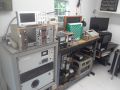
Another thing you want to have at your disposal, is a high voltage power load. I am in the fortunate position to be payed for building one for a project and to keep it afterwards. I built it just today.
IMG_20171110_155852.jpg
Cheers, Finn Hammer
There _is_ madness to my method.
Re: Criticize my HV supply design
Wood is at least a little conductive, might be problem.
-
Dennis P Brown
- Posts: 3189
- Joined: Sun May 20, 2012 10:46 am
- Real name: Dennis Brown
Re: Criticize my HV supply design
I use ceramic that are pre-drilled and tapped. These are available from electrical supply sites that handle high voltage. Also, plastic posts (easy to drill and tap for screws) or even plastic bolts work when placed under synthetic oil; then the heat load can be handled. One could use short glass tubes with epoxy to secure the screws in the tube; then place this and the resistor under oil.
Impressive work on assembling the x-former!
Impressive work on assembling the x-former!
-
Finn Hammer

- Posts: 298
- Joined: Sat Mar 05, 2016 7:21 am
- Real name: Finn Hammer
- Contact:
Re: Criticize my HV supply design
Silvio,
I use a paper laminated phenolic, due to it's superior surface tracking properties. G10 or FR4 would do fine too, I'm sure. Cotton laminated phenolic is the worst in this respect, so avoid it like the plague.
Nice work, and great overkill with that transformer.
Cheers, Finn Hammer
I use a paper laminated phenolic, due to it's superior surface tracking properties. G10 or FR4 would do fine too, I'm sure. Cotton laminated phenolic is the worst in this respect, so avoid it like the plague.
Nice work, and great overkill with that transformer.
Cheers, Finn Hammer
-
Silviu Tamasdan
- Posts: 147
- Joined: Wed Jun 28, 2006 7:17 pm
- Real name: Silviu Tamasdan
- Location: Connecticut
Re: Criticize my HV supply design
Thanks; I actually ordered some G10 sheet because it's basically good old bakelite laced with fiberglass. It's 2mm thick, I hope that it's stiff enough to support the resistors.
(edit) To be honest I was dreading making that coil, and put it off for some time. In the end though it wasn't so bad since I prepared everything carefully. I'm already thinking of the next one.
(edit) To be honest I was dreading making that coil, and put it off for some time. In the end though it wasn't so bad since I prepared everything carefully. I'm already thinking of the next one.
There _is_ madness to my method.