During startup and initial adjustments, there were a lot of arc overs inside the chamber. Everything stood up well to the abuse, except for the ionization gauge, which had its logic get scrambled. Power cycling it fixed it.
First Plasma for Bob Reite
-
Bob Reite

- Posts: 579
- Joined: Sun Aug 25, 2013 9:03 pm
- Real name: Bob Reite
- Location: Wilkes Barre/Scranton area
First Plasma for Bob Reite
First plasma adjusted for what looks most like a "star".
Current safe viewing setup. a shaving mirror on a block of wood.
Meters displaying operating voltage and current.
Close up of ionization gauge reading.
During startup and initial adjustments, there were a lot of arc overs inside the chamber. Everything stood up well to the abuse, except for the ionization gauge, which had its logic get scrambled. Power cycling it fixed it.
The more reactive the materials, the more spectacular the failures.
The testing isn't over until the prototype is destroyed.
The testing isn't over until the prototype is destroyed.
-
Bob Reite
- Posts: 579
- Joined: Sun Aug 25, 2013 9:03 pm
- Real name: Bob Reite
- Location: Wilkes Barre/Scranton area
The Next Refinement
I've been running this system on air experimenting with different voltages and pressures. The pressure seems to be very dependent on grid current (perhaps the gas expands from the heat?) I got tired of having to fiddle with so many variables at once, so after I sold an extra vacuum chamber, I used some of the proceeds to buy a motorized exhaust valve with a "14 day money back guarantee" and broken (but I made sure I could get a schematic before I bid on it) exhaust valve controller. The controller was pulled from the original installation in a hurry, all the cables were cut, including the power cord. I replaced the cord and blown fuse, and bench tested the combination. Bringing up the unit slowly on a variac showed no faults, current drain was normal, no idea why the fuse was blown. The unit actually worked except that the "error" meter never moved from full right. Found the LM308 Op amp was bad. That op amp is discontinued. But the pin out is pretty standard for an 8 pin DIP. 2 and 3 are the inputs, 6 is output 4 is - supply 7 is + supply.
Pins 1 and 8 were for the compensation capacitor on the original chip. I had an OPA604 op amp left over from an audio project, so I bent pins 1, 5 and 8 out of the way and plugged it into the LM308 socket. Unit now bench tested and aligned perfectly. I didn't have enough parts to make a long cable, so the controller lives right next to the motor as seen in the photo below.
New exhaust valve controller. The valve itself can be seen in the blurry background
Took about 1/2 hour tweaking the gain and lead on the controller to get a stable servo operation, but now I was able to tabulate meaningful data. This is still running with air. I adjusted the drive to keep the current near 10 mA and let the voltage fall where it may.
3.5 microns is at the lower edge of glow mode stability however. I'm guessing that I'm going to have to reduce the diameter of the grid to get a higher voltage at higher pressures and keep the grid current around 10 mA. My existing power supply is near the current limit, I'm going to parallel another identical 400 watt audio amp with the existing unit, with one or two ohms in series with the outputs to encourage load sharing. Stay tuned...
Pins 1 and 8 were for the compensation capacitor on the original chip. I had an OPA604 op amp left over from an audio project, so I bent pins 1, 5 and 8 out of the way and plugged it into the LM308 socket. Unit now bench tested and aligned perfectly. I didn't have enough parts to make a long cable, so the controller lives right next to the motor as seen in the photo below.
Took about 1/2 hour tweaking the gain and lead on the controller to get a stable servo operation, but now I was able to tabulate meaningful data. This is still running with air. I adjusted the drive to keep the current near 10 mA and let the voltage fall where it may.
Code: Select all
Microns        KV         mA       Fusor Input Power Watts
6.0            10         13        130
5.5            11         10        110
5.0            13         12        156
4.5            17          9        153
4.0            22          9.8      215.6
3.5            27          10       270
3.5 microns is at the lower edge of glow mode stability however. I'm guessing that I'm going to have to reduce the diameter of the grid to get a higher voltage at higher pressures and keep the grid current around 10 mA. My existing power supply is near the current limit, I'm going to parallel another identical 400 watt audio amp with the existing unit, with one or two ohms in series with the outputs to encourage load sharing. Stay tuned...
The more reactive the materials, the more spectacular the failures.
The testing isn't over until the prototype is destroyed.
The testing isn't over until the prototype is destroyed.
-
Bob Reite
- Posts: 579
- Joined: Sun Aug 25, 2013 9:03 pm
- Real name: Bob Reite
- Location: Wilkes Barre/Scranton area
Anti corona ball
The more reactive the materials, the more spectacular the failures.
The testing isn't over until the prototype is destroyed.
The testing isn't over until the prototype is destroyed.
-
Bob Reite
- Posts: 579
- Joined: Sun Aug 25, 2013 9:03 pm
- Real name: Bob Reite
- Location: Wilkes Barre/Scranton area
Gas System Built
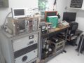
Today's Image de Jour.
The mass flow controller and electrolyzer. The big old Lamba supply in back is for plus 12 volts to run the mass flow controller and input to the home built 1.5 to 3.0 volt supply for the PEM cell. The meter is a 50 microamp meter, calibrated "0-30", which is OK for my use as the PEM cell is rated to draw 2.5 A at 3.0 V. 2.1 feet of 24 ga wire is the shut to get the meter to read 3 A full scale. I have not filled the gas collection vials with oil yet, nor added heavy water to the PEM cell yet. First order of business is getting the mass flow controller to work OK with air. The DMM monitors the flow rate. It is very touchy, the 10 turn pot is almost at 1% of total rotation. Our fusors require very low flow rates indeed! Glad I put in a 5 K pot, I'll add resistance in series with the 5 volt feed to the pot to make the range more usable. Hopefully the mass flow controller will work at such low volumes. If it doesn't I'll have to take another approach.
The more reactive the materials, the more spectacular the failures.
The testing isn't over until the prototype is destroyed.
The testing isn't over until the prototype is destroyed.
-
Dennis P Brown
- Posts: 3189
- Joined: Sun May 20, 2012 10:46 am
- Real name: Dennis Brown
Re: First Plasma for Bob Reite
Very impressive set up and the corona sphere for the feed through was a good idea. I'd think more details of your Deuterium generation system would be of great interest for many here; especially the mass flow controller since that was a topic of late.
-
Bob Reite
- Posts: 579
- Joined: Sun Aug 25, 2013 9:03 pm
- Real name: Bob Reite
- Location: Wilkes Barre/Scranton area
Re: First Plasma for Bob Reite
I'll post more details on the gas handling system once it is fully debugged and operating correctly.
The more reactive the materials, the more spectacular the failures.
The testing isn't over until the prototype is destroyed.
The testing isn't over until the prototype is destroyed.
-
Bob Reite
- Posts: 579
- Joined: Sun Aug 25, 2013 9:03 pm
- Real name: Bob Reite
- Location: Wilkes Barre/Scranton area
Some set backs.
I found out why the mass flow controller was so "touchy". Instead of the 10 sccm controller I was expecting, I received a 10 L/m unit! 1000 times the flow! (Don't know why I didn't notice when I first unpacked it) Working on a trade for what I really need. The VCR fittings I need still aren't here yet. Chances are, I won't be able to try for real fusion until after Labor Day weekend.
The more reactive the materials, the more spectacular the failures.
The testing isn't over until the prototype is destroyed.
The testing isn't over until the prototype is destroyed.
-
Bob Reite
- Posts: 579
- Joined: Sun Aug 25, 2013 9:03 pm
- Real name: Bob Reite
- Location: Wilkes Barre/Scranton area
New Flow Controller Installed, Gas System Running
I have done three fusion runs now with detectable neutrons. I will post a new message in the required format sometime on Sunday, 14-Sept.
Last edited by Bob Reite on Sun Sep 14, 2014 7:45 pm, edited 1 time in total.
The more reactive the materials, the more spectacular the failures.
The testing isn't over until the prototype is destroyed.
The testing isn't over until the prototype is destroyed.
-
Andrew Robinson

- Moderator
- Posts: 688
- Joined: Sun Aug 11, 2013 1:54 am
- Real name: Andrew Robinson
- Location: Raleigh, North Carolina
- Contact:
Re: First Plasma for Bob Reite
Nice work Bob, I'd love to see the pin out and control schematic for your flow controller. My group has been talking about a similar setup and discussing the electronics side to a non manufacture made controller.
I can wire anything directly into anything! I'm the professor!