Hello, everyone.
In the past week, I have made substantial progress on my high voltage metering system.
In this test, I used a 33 Gigaohm resistor to serve as a replacement for the outer and inner grid.
The high voltage source is a half rectified 9 kV 30 mA NST.
For the resistor divider, I used 3x33 Gigaohm resistors in series with a 10 Kiloohm resistor.
Before the test, I had a minor problem where I couldn't measure the voltage without unplugging the current meter.
This issue was later fixed by reversing the polarity on the voltage and current meter.
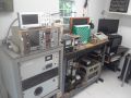
Demo Fusor Voltage and Current Measurment Test
- Filippo_Passeri
- Posts: 11
- Joined: Sun Jun 12, 2016 7:10 pm
- Real name: Filippo Passeri
- Location: Czech Republic
Demo Fusor Voltage and Current Measurment Test
"Will you remember the famous men who have to fall and then to rise again,
So take a deep breath, pick yourself up, dust yourself off, and start all over again."
-Frank Sinatra Jr
So take a deep breath, pick yourself up, dust yourself off, and start all over again."
-Frank Sinatra Jr
- Rich Feldman
- Posts: 1471
- Joined: Mon Dec 21, 2009 6:59 pm
- Real name: Rich Feldman
- Location: Santa Clara County, CA, USA
Re: Demo Fusor Voltage and Current Measurement Test
Good work there!
I bet 9 out of 10 demo fusors never get any high voltage metering.
Yours looks very nice. Are the little digital panel meters battery-powered?
Beware that each resistor "product series" comes with a maximum power rating and a maximum voltage rating.
The two are independent.
For ohm values near the high end of the series, it's common to hit the voltage rating long before the power rating.
If your 33 GΩ resistors have a 2-watt power rating and are of ordinary size for that, then their working voltage rating is probably 500 V. If so, then your picture is evidence of resistor abuse, but not serious abuse. Not like putting them to work at 2½ times their rated power!
The usual remedy is to make the HV metering resistor from a larger number of R's. Or get special R's with extra high voltage ratings. This has been discussed many times on the forum, if not in one of the FAQs.
Happy fusing.
-Rich
All models are wrong; some models are useful. -- George Box
- Filippo_Passeri
- Posts: 11
- Joined: Sun Jun 12, 2016 7:10 pm
- Real name: Filippo Passeri
- Location: Czech Republic
Re: Demo Fusor Voltage and Current Measurment Test
Thanks for your input.
I have realised I have made a foolish mistake.
I mistook gigaohms for megohms, so instead of 33 GΩ resistors, I have 33 MΩ resistors.
I have found the appropriate datasheet that states these resistors have a maximum voltage rating of 10 kV.
So there is no worry there since the maximum voltage my NST can achieve is around 4 kV.
The power rating for these resistors is 1 Watt. Assuming voltage is 4 kV.
I have roughly calculated that the maximum power going through the entire series is around 0.16 watts.
(4000 V/ 99000000 Ω) * 4000 V = 0.1616 W
So there is no real problem in energy dissipation unless I have forgotten some other forces or I made a mistake in my calculations.
You can see the datasheet on the resistors (VR68) here: http://www.vishay.com/docs/28907/vr25vr37vr68.pdf
In the first picture, you can see the digital panels are being powered by a 12-volt PC power supply. A socket 9-volt charger initially powered it.
The reason why you see a power supply instead of the charger is that before the test I had major problems in the metering system where the
voltage meter was glitching out of control every time I plugged in the current meter.
I noticed that the glitching numbers were similar to the input voltage (9 volts) so I figured that it maybe had something to do with the socket charger.
Out of sheer paranoia, I cut the power cord and installed the power supply. Which of course didn't solve the problem.
The solution was later achieved by reversing the input wires on each panel.
I plan to switch to the socket charger since it's more ergonomic and aesthetic.
"Will you remember the famous men who have to fall and then to rise again,
So take a deep breath, pick yourself up, dust yourself off, and start all over again."
-Frank Sinatra Jr
So take a deep breath, pick yourself up, dust yourself off, and start all over again."
-Frank Sinatra Jr
- Richard Hull
- Moderator
- Posts: 15037
- Joined: Fri Jun 15, 2001 9:44 am
- Real name: Richard Hull
Re: Demo Fusor Voltage and Current Measurment Test
I would modify Rich's estimate to say 99 out of 100 demo fusors never have full, dedicated, accurate voltage and current readouts. You have done a fine job in you metering efforts. you can learn a lot of information by combining what you see with the varying pressures and voltages and currents in a demo fusor. I made two demo fusors in 1997 and 1998 studying all parameters of the glow for over one full year while reading von Engels book "Ionized Gases". Few here have ever done that long a time lashed to a demo system trying to understand what is going on in detail and performing experiments.
Richard Hull
Richard Hull
Progress may have been a good thing once, but it just went on too long. - Yogi Berra
Fusion is the energy of the future....and it always will be
The more complex the idea put forward by the poor amateur, the more likely it will never see embodiment
Fusion is the energy of the future....and it always will be
The more complex the idea put forward by the poor amateur, the more likely it will never see embodiment
- Dennis P Brown
- Posts: 3190
- Joined: Sun May 20, 2012 10:46 am
- Real name: Dennis Brown
Re: Demo Fusor Voltage and Current Measurment Test
Nice setup with the NST; besides the value in learning about how to measure high voltage properly, you have added a very useful device to your setup. Excellent work; measuring voltage of a real fusor is similar but current is another matter and read the FAQ's on that subject; that is, once you decide on (or if you decide to at all) construction of a fusor grade power supply.