Hello Everyone,
Today I got my demo fusor working. Following are pictures taken during the run.
Plasma pictures:
The Cathode HV tank (taken out of a High frequency X-Ray machine) has a 6.2kohm over 10Mohm voltage divider. I assume it outputs 5volts for its logic circuits measuring maximum voltage.
Doing simple math, HV*(6.2k/(10M+6.2k))=5v. HV= (5*(10M+6.2k))/6.2k =~ 8070v. The tank has a total ov 9 capacitor in series.
So 8070v x 9 = 72630v =~ 72000v. In this picture, I had the meter set to 2.5volt range. So a full scale will read 72000v/2 = 36000v on full scale.
The voltage reading on the fusor at around 31.5mA (according to shunt resistor voltage) is 0.1v which corresponds to (0.1*(10M+6.2k))/6.2k =~ 161.4v x 9 =~ 1452.5v
voltage across 100ohm shunt resistor is around 3.15v. V=IR. I=V/R. I= 3.15v/100ohm = 31.5mA
The vacuum pressure is.. Umm. all the way down.
The central grid mounted on a sparkplug. Please excuse all the sloppy workmanship,
Light blues are simple blutacks bought from stationary for quick sealant. The dark blue ones are silicon gasket makers.
The base plate is 10mm acrylic and the cover is around 3mm thick salad bowl.
The HV tank, IGBT circuit and High frequency driver circuit running at 100kHz. The 100kHz pulse
is supplied by the function generator. These high frequency circuits was initially used to run my Continuous Wave
Tesla Coil.
Plasma at much lower voltage levels.
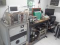
And finally, my messy overall setup. Note that there are unutilized equipment's on the table as well.
After this my plans are to house keep my setup and save up for a micron pressure gauge to build an actual fusor. Living in a third world country will take some time to save up. But I strive to gain some knowledge that
is always more valuable than money.
Thank you for reading my post. Any help for my future work in building an actual fusor is highly appreciated.