Vacuum Chamber
The main chamber is MDC 8" CF, with 2.75" CF ports connecting the feedthrough, gauges, deuterium line, pump line, etc. The main 4-way cross has an 8" window and an 8" chamber door. Once I install the deuterium line and build a steel structure around it I will integrate the electronics and secondary systems to make it one portable unit (2-3 guys could pick it up, it'll probably need wheels).
- Chamber WIP 3
- Chamber WIP 2
- Chamber WIP 1
Pfeiffer TPH60 60 l/s turbopump with TPG121 controller. Seems to be in great condition although I don't know the bearing condition (the blades do spin freely) or oil levels. The backing pump is a 3cfm two-stage, nothing special but it should get the job done.
- TPH60 turbo pump
- Backing pump
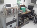
Control Center
Variac to control input to the x-ray transformer, e stop button, neutron count monitoring, and multi-feed camera viewing.
- Control center
I'm using a soviet He3 detector tube connected to a pc digital oscilloscope and corresponding software. I'm getting average background counts of 5-7.5 cpm on average, and gamma rejection seems to be working well.
- СИ-19Рdetector tube
I've been planning to test a variety of different grid designs, so I'm building a "hotswappable" mounting system where grid designs can be changed in seconds, also thanks to the 8" door.
- Hotswappable grid bay
A pfeiffer balzers PKR251 compact full range gauge (cc + pirani) relays to a pfeiffer singlegauge controller. At atmospheric it always reads around 20 torr. Could the gauge be malfunctioning? ... it has a small dent on the magnet housing.
- Pfeiffer singleGauge
I still have to build a power supply out of the xray transformer. While my wiring and connectors are rated to 75kV the chamber feedthrough is a standard 30kV. Is it possible to modify it to take 60kV?
EDIT:
- New XRT schematic
The deuterium line includes an electrolysis unit of Andrew Seltzman's design, a drierite stage, a micron filter, a 1 liter storage tank (might also add a 500cc tank) and two needle valves to regulate flow.
- Deuterium line WIP
- Construction_1
- Construction_2
- Construction_3