I apologize for not posting the construction progression of my fusor. I have just read the requirements for claiming fusion, and see that I should have been doing that. Hopefully I can make up for that with this detailed report.
I have made extensive use of this web site and doubt that I ever would have been able to make a fusor without the information provided in the forums.
I Joined fusor.net Feb 2016, and have made only 7 posts.
SUMMARY
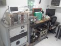
Here is a picture of the Fusor. I started working on this January 2016. Looking back at my order history the first part ordered was "Allanson 15000 Volt 60 Ma Neon Sign Transformer", on Jan 4, 2016. It turned out this NST was not useful because when connected to a dummy load it's ground fault circuit breaker tripped, and there is no way to defeat the GFI on this NST. I later acquired a dental X-Ray transformer.
- The upper left is the image from the camera.
- The values shown in the black area near the top are self explanatory, except for NPHT, which stands for Neutron Pule Height Threshold. Pulse heights larger than this value are counted as neutron events.
- The Summary graph at the bottom is a 300 second plot of the voltage, current, neutron counts/minute, and D2 pressure.
- The Neutron ADC graph shows the pulse data collected from the ADC during a 1 second interval. Only pules that are larger than the NPHT are displayed.
- Time Span = 1:30 minutes (20:20:20 to 20:21:50)
- Average Voltage: 30 KV
- Average Current: 6 mA
- Average D2 Pressure: 15 mT
- https://drive.google.com/file/d/0B3Q10q ... sp=sharing
- https://drive.google.com/file/d/0B3Q10q ... sp=sharing
Power Supply
I used a circuit similar to the what is described here viewtopic.php?f=29&t=4405 with the following changes:
- a dental X-Ray Transformer is used instead of a Neon Sign Transformer
- used 3 20KV 2A diodes in series
- no capacitor
- different metering resistor values, described below.
- added a ballast resistor.
The X-Ray transformer fits snugly in a 1.5 gallon container, which is filled with 1 gallon of low viscosity mineral oil. I did not try to draw a light vacuum and add the mineral oil under the vacuum. Instead I did gently shake the container to attempt to dislodge bubbles (I didn't see any bubbles discharged), and the transformer has been resting in the mineral oil for months without being used while I was working on other areas. I did have a problem with the mineral oil slowly syphoning through the high voltage wires, This problem was solved by adding the vertical black wires on the end of 2 diode chains, and attaching the HV wire at a greater height than the mineral oil.
I used a 50K ohm 100W watt ballast resistor. At 40 mA, the power dissipated in the ballast resistor would be 80 watts. At a more typical fusor current of about 10 mA the power dissipated would be 5 watts, and the voltage drop is 500 volts.
The power supply has only been used under load for about 10 minutes so far. I am concerned that the X-Ray transformer may have some air bubbles and/or is being run at higher currents and duration that it was designed for. Therefore I have kept the fusor runs short.
The resistor used to measure current is 100 ohm 10 watt 5%. A panel meter and an ADC are both connected to this resistor. The ADC is connected to a Raspberry Pi computer. When the current is 10 mA the voltage across this resistor will be 1 V, which is a reading of about 200 on the ADC.
The voltage divider, used to measure the high voltage, is made of a 1G ohm resistor and a 100K ohm 2 Watt 1% resistor. A panel meter and an ADC are connected to the 100K ohm resistor. At 30 KV the voltage across the 100K resistor will be 3V and the ADC reading will be about 600. The 1G resistor was purchased from http://www.highvoltageresistors.biz/400 ... 60081.aspx and is specified at 60 KV and 13.5 watts.
The software that processes the date from the ADC computes an average over 1 second. The panel meters must also contain a built-in mechanism to average because the values they display are stable.
I was concerned that because a large 100K ohm resistor is used in the voltage divider, the input impedance of the panel meter and the ADC would affect the reading. The panel meter has 10M ohm input impedance, and the ADC has a 2M ohm input impedance. Using the formula to add parallel resistances of the panel meter, the ADC and the 100K ohm resistor yields 94K ohm. To account for this the software uses 94340 instead of 100000 when calculating the value of the high voltage. The KV panel meter will read about 5% low.
A problem I'm having is when the Raspberry Pi is turned on (which provides power to the USB ADC), the KV panel meter reading changes from 0.0 to -1.4. This Raspberry Pi is powered by a battery because I had suspected problems due to ground loops that might be resolved by using a battery for the power source. The software running on the Raspberry Pi compensates for this by adding 1.43, so that the software will display 0 KV when the HV power supply is turned off.
The vacuum system is comprised of:
- Welch 1402, Belt Drive Rotary Vane Dual Stage Mechanical Vacuum Pump, 5 CFM
- 4 way KF-25 cross, with connections to: (1) Welch forepump, (2) Air admittance vent valve, (3) KF-25 bellows valve, leading to diff pump, (4) Thermocouple gauge (Varian 531)
- Varian HSA Diffusion Pump, air cooled
- CF 3.38" Manual Bellows Angle Valve, connecting the Diff Pump to the Vacuum Chamber
- Gum Rubber Vacuum Hose Tubing,
- KF-25 to Rubber Hose adapters
- 90 degree Stainless Steel elbow, 1" tube size
Even now the Welch pump is still dirty on the inside, and the pump oil turns brown after being used. I should change the oil again soon. Currently the Welch Forepump can pump the chamber down to about 20 mTorr.
The Varian HSA Diffusion Pump is air cooled, and is charged with 50 mL of KJLC 704 Diffusion Pump Fluid. The diff pump heater is plugged in to a current meter so that I know it is working. The heater is 115V, and the meter reads 2.7A. It takes 15 minutes for the oil to heat up and the diff pump start pumping. The cool down time for this pump is 40 minutes.
The thermocouple gauge is a Varian 531, and controller is Varian 804-A. The controller did not come with a cable. I purchased the cable from Dunimay Stockroom, they make the cable so it takes a few extra days. The controller has a knob to select one of 5 sensors. The switch contacts needed to be cleaned, so I opened the box, cleaned the switch with contact cleaner, and it works fine now. I calibrated the TC Controller against the Pirani Gauge. There is a calibration control on the rear of TC Controller.
The chamber is made of 2 6" stainless steel hemispheres connected to each other with CF flanges (8" OD, 6" Tube Bore). There are 5 chamber ports:
- vacuum port: 3.38" CF Half Nipple, with 2" OD Tube
- electric feed through: 2.75" CF Half Nipple with 1.5" OD Tube
- view port: 2.75" CF Half Nipple with 1.5" OD Tube
- gas inlet port: 1.33" CF Half Nipple with .75" OD Tube
- pressure gauge port: KF-25 Half Nipple with 1" OD Tube
- room was left on the right side of the chamber for the HDPE moderator and Neutron Detector
- the Viewport is positioned in the back of the chamber, and at a downward angle so the X-Rays are directed into the ground
- there are no ports at the bottom of the chamber, so that if a pieces of the electric grid were to break off it would not fall into a port
- the gas inlet port is on the opposite side of the chamber from the vacuum port, so that the gas will fill the chamber prior to being evacuated through the vacuum port
- the ports are located so that clearance is available to insert the bolts in the large CF flanges that join the 2 hemispheres.
A Kurt J Lesker 275i Series Convection Vacuum Gauge, with KF-25 connection and Log-Linear analog output is used to measure chamber pressure. This is a "convection enhanced Pirani Gauge", with a range of 0.1 mTorr to just above atmosphere. This gauge has a digital readout and an analog output. A control on the gauge is used to calibrate the zero point and atmospheric pressure. I have connected the gauge's analog output to an ADC see Data Acquisition below. The gauge's manual provides conversion tables to convert the analog output voltage to pressure for various gases. The Data Acquisition software implements the D2 and N2 conversion tables.
Fortunately I had worked with someone who is now the owner of a machine shop. Most of what they do is CNC Turning & Milling, however they also have an older milling machine suited to making the holes in the hemispheres, and access to a welder who has done many vacuum chambers. I had originally thought that the holes would be drilled in the SS hemispheres, and that the holes would be smaller than the ports, and that the ports would be welded on the outside. The machine shop used a better approach:
- attached the large CF flanges to each hemisphere, and bolted metal rings on the 2 large CF flanges to protect the knife edge
- milled the holes in the chamber so that the fittings would snugly fit in the holes
- welded the fittings on the inside
I used the Logictech HD Laptop Webcam C615. I chose this webcam because it's features include:
- Premium autofocus for razor sharp images, even in close-ups
- Record clear videos even with dim or poorly backlit settings thanks to automatic light correction
The images recorded while the fusor is running shows random sparkles. I'm not sure what causes the sparkles, perhaps they are due to the X-Rays.
The Data Acquisition software configures the webcam for 640x480 images, and provides pan and zoom capability, via keyboard commands, to select a subset of the 640x480 to be displayed.
D2 Gas Feed
Series of components
- D2 Lecture bottle,
- Single Stage Regulator, with needle valve and hose barb outlet
- Flow Restrictor, details below
- Bellows Valve connecting to the chamber
- closed off the input to the flow restrictor using barbed tubing plug
- opened the gas valve and pumped down the chamber using just the forepump to about 20 mTorr
- removed the tubing plug (actually cut it off) to allow atmosphere to enter the flow restrictor
- waited for the chamber pressure to stabilize
- note the pressure
Hoping to achieve a lower pressure I built a second Flow Restrictor using 100 feet of the .020" ID micro bore tubing wound on a small cylinder. The ends of the tubing connected to a 1/8" hose barb adapter. This was also tested and also resulted in a pressure of about 200 mTorr.
Finally I connected the 2 Flow Restrictors in series, and testing this configuration yielded a pressure of 80 mTorr, which seems okay.
My D2 lecture bottle currently has about 600 psig. I had wasted some of the D2 during initial tests, before I realized just how little gas is in the lecture bottle, and became more careful not to waste it. A D2 lecture bottle at 850 psig contains just 25 L, or 0.9 cubic feet of gas at atmospheric pressure.
The regulator used is a "Harris HP704-015-170A Lecture Bottle Pressure Regulator, 0-15 psig, Brass" single stage regulator with Needle Valve. It is my understanding that some regulators will not handle the outlet being exposed to vacuum. The needle valve allows me to isolate the regulator from the vacuum.
Additional Info
- CGA is abbreviation for Compressed Gas Association
- http://www.airproducts.com/~/media/file ... ram-31.pdf Provides an overview of Cylinder Outlet Connections. This doc provides torque guideline of 10 ft-lb recommended for CGA 170 with washer
- http://www.mathesongas.com/pdfs/product ... -Chart.pdf Provides cylinder information for various gas types. Indicates D2 cylinder can use CGA350 or CGA170. And "NOTE: The CGA 170 is authorized for non-corrosive gases packaged in lecture bottles. The CGA 180 is authorized for all gases packaged in lecture bottles.
- Whenever the CGA 170 regulator is removed and re-attached to the cylinder a new washer should be used. Washers can be obtained from: https://store.mathesongas.com/cga-washers-teflon/
- A disadvantage of a single stage regulator is that the output pressure does not remain constant; instead as the high pressure side of the regulator drops in pressure, the output pressure of the regulator increases.
The grid was constructed of a single Tantalum wire, diameter 0.065". The diameter of the grid is approximately 1.5", which is the maximum size that will fit through the electric feedthrough port.
I first practiced constructing a model of the grid using hookup wire. When satisfied with the technique I repeated the procedure with the Tantalum wire. A circular template was used to help bend the wire into a loop.
To insulate the stalk I used 2 nested Alumina Ceramic Tubes. The inner tube is 1/8" ID and 1/4" OD; and the outer tube is 1/4" ID and 3/8" OD. The Alumina Ceramic tubes were easy to cut using a small diamond circular saw blade. I made a jig to securely hold the tube, brought it outside, wore mask and goggles, and performed the cuts.
The grid was attached to the electric feedthrough by tightly wrapping the Tantalum wire around the feedthrough after carefully measuring for the desired location. I used vise grips to further tighten the wraps, to ensure the grid would not slide off during operation of the fusor. The inner Alumina tube rests on the top of the wraps, and the outer tube extends down to cover the wraps. The outer tube is a tight friction fit on the inner tube.
The pictures below illustrate the construction process. Shown is the model made of hookup wire, and leftover Alumina tubing.
I am using an SI-19N He3 Neutron Detector Tube. I have seen information which says this is a corona mode detector. However the seller had tested this tube at a lower voltage using a proportional counter. I am using this detector at 1700 volts, where it works as a proportional detector. In the 2000 - 2800 volt range this detector is documented to work in corona mode, which would require more current than my Ludlum 2929 could provide.
The SI-19N is surrounded by 3-4 inches of HDPE on all sides to slow the fast neutrons that are released by the fusor to a speed that the neutron detector tube can detect.
The SI-19N Neutron Detector is connected to a Ludlum 2929 Dual Channel Scaler. The Ludlum documentation states this Scaler is usually used with an Alpha/Beta Sample Counter; but it can also be used with a proportional detector. This Scaler has a BNC connector on the rear that provides the final amplifier stage output. I have connected from this BNC connector to an ADC converter as described in the next section. The Alpha/Beta LED counter displays on the Ludlum 2929 are not being used.
Two Raspberry Pi computers are being used:
1) Computer Name = rpi_data, Program Name = get_data.
- reads data values from the Voltage, Current, Pressure, and Neutron Tube ADC inputs
- analyzes the data, for example identifies pulses from the Neutron Tube input
- the analyzed data is sent to the other Raspberry Pi via Wifi
- powered by a battery, because I was having trouble with AC ripple, which I suspected was caused by the Raspberry Pi power adapter.
- receives the analyzed data over Wifi from rpi_data
- reads the camera image from the USB webcam
- displays the camera image, data values, and graphs
- accepts user input for various controls, including selecting the Neutron Pulse Height Threshold (NPHT), and adjusting the camera image pan and zoom
- records the analyzed data to a file so it can be viewed later in Playback mode
- can run in Playback mode to examine the recorded data at a later time.
The ADC for the Neutron Tube data needs to be high speed because the pulses are only a couple of microseconds duration. I found a reasonably priced ADC that can collect data from a single input channel at 500K samples per second. I was at first concerned that the pulses might be too narrow to be properly measured with this ADC, so I tried some simple circuits to widen the pulse. It turned out that these simple circuits did not do what I expected, and that simply directly connecting the Ludlum 2929 amplifier output to the ADC input works well.
I did have a problem with the low speed ADC (which reads the Voltage, Current, and Pressure) interfering with the High Speed ADC (the one reading the Neutron Amplifier Output data). The High Speed ADC FIFO would fill and enter an error state. I coded the software to detect this error and restart the high speed ADC; this happens twice per second. So instead of getting 500K samples per second, the software is receiving ~475K samples per second, which still is okay.
The software is freely available on github, and is licensed under the MIT License. The recorded data file from my first fusion run is available on Google Drive. The display program will run on a 32bit or 64bit Linux. For example I run the display program on either a Raspberry Pi or Fedora-20/x86_64 desktop computer. If you would like to try the display program these are the steps that can be used to build, install, and run the program on Fedora-20. It shouldn't be difficult to build and run this software on other versions of Linux as well. If you need help, send me an email, my email address is in the about.h file.
Code: Select all
# install additional software development packages
yum install SDL2-devel SDL2_ttf-devel SDL2-mixer-devel
yum install libjpeg-turbo-devel libpng-devel
yum install gnu-free-mono-fonts

# clone the git repo
cd ~
git clone https://github.com/sthaid/proj_fusor.git

# build the display program
cd proj_fusor
make display

# Download the 248M fusor run data file by browsing to:
#   https://drive.google.com/file/d/0B3Q10qVwU0_FZmc2VWZrSlNxQUU/view?usp=sharing

# run the display program
display -h                                        # help on program options
display -p ~/Downloads/fusor_170724_192651.dat    # then use '?' for help
PROCEDURES
The following procedure focuses on the major steps. Steps dealing with the electronics are omitted. If you are interested see the following link for the full procedure that I used. https://drive.google.com/file/d/0B3Q10q ... sp=sharing
Initial Conditions
- The 3 Bellows valves are closed.
- Air admittance vent valve is open.
- Regulator needle valve is closed.
- Regulator pressure adjustment knob rotated counterclockwise and turning freely.
- D2 lecture lecture bottle valve is closed.
- Variac is turned off and set to 0 volts.
- Open and then close the D2 lecture bottle valve, this will pressurize the inlet side of the regulator with enough gas to run the fusor. It is important to run with the D2 lecture bottle valve closed to avoid accidentally wasting the deuterium gas.
- Turn the regulator adjustment handle clockwise until the regulator outlet gauge reads about 2 psig.
- Turn on the diffusion pump fan.
- Close the Air admittance vent valve.
- Power on the forepump and verify the pressure quickly drops to 30 mTorr.
- Open the forepump bellows valve and verify pressure again reaches 30 mTorr. This step pumps down the diff pump.
- Open throttle valve and verify pressure again reaches 30 mTorr. This step pumps down the chamber.
- Open gas valve, and wait about 10 minutes for pressure to reach about 25 mTorr. This pumps down the gas leak lines up to the regulator's needle valve.
- Power on Diff pump heater.
- Wait about 15 minutes for the chamber pressure (Pirani gauge) reading to reach about 0.2 mTorr. What I have observed is for the first 14 minutes the chamber pressure fluctuates but remains high; then the pressure drops quickly reaching 0.2 mTorr in a couple of minutes.
- Close throttle valve until chamber pressure stabilizes at about 1 mTorr,
- Open needle valve on D2 regulator, and wait for D2 chamber pressure to stabilize, at hopefully near 15 mTorr.
- Adjust throttle valve for 15 mTorr D2 chamber pressure.
- Turn on the Geiger Counter and check it occasionally while the high voltage is on.
- Turn on the Variac and slowly increase the voltage until the plasma ignites. At this point I backed off the voltage and slowly brought it back up again and the plasma re-ignited, this time drawing less current. I had also experimented with different pressures before settling on 15 mTorr.
- Check Neutron CPM readout, and increase voltage if more CPM is desired.
- After a minute or two reduce the Variac setting to 0 volts, and turn off the Variac.
- Turn the regulator pressure adjustment knob counterclockwise until turning freely.
- Wait for the regulator outlet gauge to drop to near 0 psig and close the regulator's needle valve.
- At this point their still may be a substantial pressure reading on the regulator's inlet gauge. If there is enough pressure on the inlet gauge then the next time the fusor is used it may not be necessary to use more D2 gas from the lecture bottle.
- Isolate the chamber by closing the gas inlet bellows valve. Wait a few seconds for the chamber to pump down. And then close the throttle bellows valve.
- Turn off the diffusion pump heater and note the time. IMPORTANT: leave the diff pump fan and forepump on.
- Wait 40 Minutes for the diffusion pump oil to cool down.
- Close the forepump bellows valve.
- Turn off the forepump, and quickly open the air admittance vent valve.
- Turn off the diffusion pump fan.