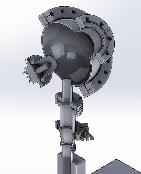
It looks like we are switching our HV feedthrough. The one we currently have is an older style. Looks similar to this:
https://i.ebayimg.com/images/g/AbsAAOSw ... s-l500.jpg The two ceramic-isolated terminals are on the vacuum side.
The one we plan on buying now,
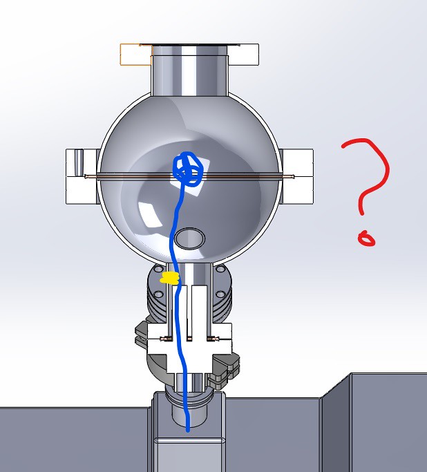
Lesker EFT0513253 has a much more desirable connector on the vacuum side, a 0.25 in. diameter, 4 in. length copper pin.
Conveniently, ceramic beads already exist that would be able to slide over this pin and provide insulation. However... this pin by itself is not going to be long enough to reach the middle of our spherical chamber where we want the grid to be.
I considered extending this copper pin by the welding of a 3/16 inch threaded rod, made of stainless steel to the end. The reason for the threading is we want to easily unscrew/screw in different grids via hexnut. Then, ideally, the beads could slide over the copper pin and the threaded rod, up to where our grid would be (we are buying 1mm titanium wire). However, I don't have any experience welding and upon research, the welding of Stainless Steel to copper is difficult. Aluminum threaded rods exist, but pose a similar issue if I understand correctly.
My next thought was to somehow thread the copper pin, then attach a threaded SS pipe to extend the length (
viewtopic.php?f=11&t=12375&p=82149#p82149), but then getting ceramic beads to fit over it is a conundrum.
Any more experienced ideas on how to approach this? In addition to the 4 inches the pin gives, we'd need another 4 or 5 inches.


