Page 1 of 1
HV feedthrough & chamber insulation
Posted: Sat Dec 08, 2018 2:46 am
by Taylor Shead
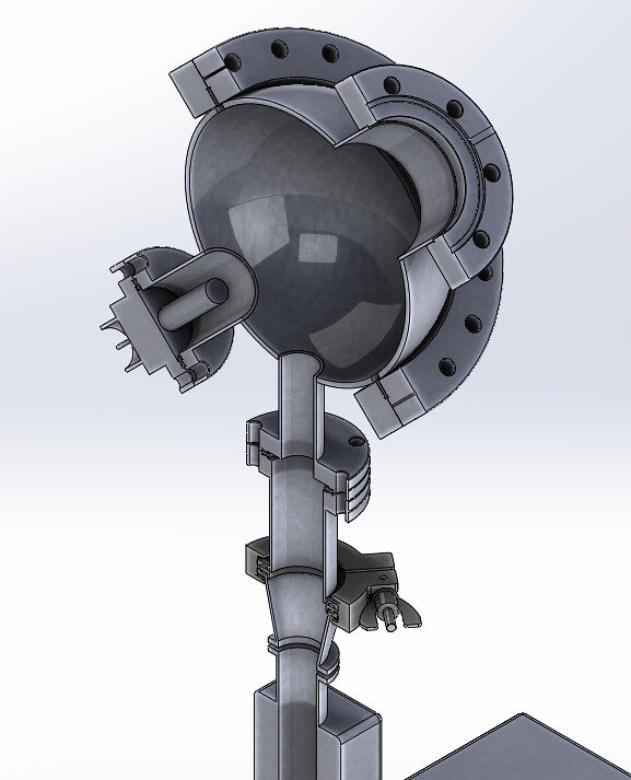
So I modeled our fusor in SolidWorks after getting the correct measurements from a bunch of eBay parts (also the reason the vacuum attachment is wonky). It is not done but it is coming along nicely.
Our setup thus far:
My question:
After proper vacuum get pulled on it, won't the HV line all the way to the grid need insulation? What are people using that's demo fusor rated?
Our feed through is rated to 20kV (iirc) but can I just surround the line the the grid with PVC and hot glue it to the feed through? Will I need something more complicated?
Envisioned without insulator (EMF goes to chamber wall after exiting feed through):
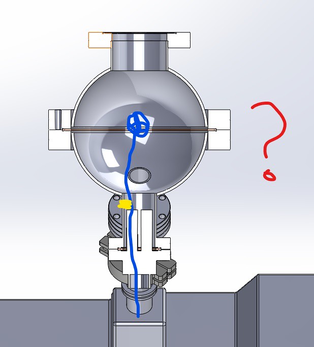
Envisioned with insulator (EMF goes to chamber wall after reaching grid):

Re: HV feedthrough & chamber insulation
Posted: Sat Dec 08, 2018 11:19 am
by Richard Hull
Most people use alumina ceramic tubing on the grid stalk. No plastic or hot glue allowed.
Richard Hull
Re: HV feedthrough & chamber insulation
Posted: Sun Dec 09, 2018 4:22 am
by Taylor Shead
So how do I surround the already ceramic feedthrough with more of the stuff? I’ll post an image of our feedthrough when I can to help but on the end are nuts threaded on to metal. I think it’s pretty standard.
I just don’t know how to interface with the longer insulator and what to search for to purchase. Or can I make one?
Re: HV feedthrough & chamber insulation
Posted: Sun Dec 09, 2018 9:11 am
by Dennis P Brown
You could run an other ceramic tube down the HV lead and use a good ceramic compound/glue to locked it in place. I do that but room is always an issue. If that isn't possible your choices are limited: get a new feed-thru, machine the existing one to handle a thicker ceramic cover - if possible, or (like I do), make your own.
Re: HV feedthrough & chamber insulation
Posted: Thu Jan 31, 2019 1:43 pm
by Ben_Barnett
It looks like we are switching our HV feedthrough. The one we currently have is an older style. Looks similar to this:
https://i.ebayimg.com/images/g/AbsAAOSw ... s-l500.jpg The two ceramic-isolated terminals are on the vacuum side.
The one we plan on buying now,
Lesker EFT0513253 has a much more desirable connector on the vacuum side, a 0.25 in. diameter, 4 in. length copper pin.
Conveniently, ceramic beads already exist that would be able to slide over this pin and provide insulation. However... this pin by itself is not going to be long enough to reach the middle of our spherical chamber where we want the grid to be.
I considered extending this copper pin by the welding of a 3/16 inch threaded rod, made of stainless steel to the end. The reason for the threading is we want to easily unscrew/screw in different grids via hexnut. Then, ideally, the beads could slide over the copper pin and the threaded rod, up to where our grid would be (we are buying 1mm titanium wire). However, I don't have any experience welding and upon research, the welding of Stainless Steel to copper is difficult. Aluminum threaded rods exist, but pose a similar issue if I understand correctly.
My next thought was to somehow thread the copper pin, then attach a threaded SS pipe to extend the length (
viewtopic.php?f=11&t=12375&p=82149#p82149), but then getting ceramic beads to fit over it is a conundrum.
Any more experienced ideas on how to approach this? In addition to the 4 inches the pin gives, we'd need another 4 or 5 inches.