Andrew,
Can't wait to see your results..
I like your setup, the grid has two advantages, a) it is cooled, and b) it has a thick radius, thereby reducing the voltage gradient around the grid wires (less likely electron emission from the surface.)
Hope to get the stats for my Q list soon..
Don't forget to count the power to the ion guns
Steven
Anode layer ion source. Operation pictures
-
Steven Sesselmann

- Posts: 2128
- Joined: Wed Aug 10, 2005 9:50 pm
- Real name: Steven Sesselmann
- Location: Sydney - Australia
- Contact:
Re: Final Design Modifications. Faraday Cup Measurements
http://www.gammaspectacular.com - Gamma Spectrometry Systems
https://www.researchgate.net/profile/Steven_Sesselmann - Various papers and patents on RG
https://www.researchgate.net/profile/Steven_Sesselmann - Various papers and patents on RG
-
Chris Bradley

- Posts: 2930
- Joined: Fri May 02, 2008 7:05 am
- Real name:
Re: Anode layer ion source. Operation pictures
There's no mistaking this is serious, well crafted kit.
I'm still unsure about what the 'wiring diagram' is going to look like. In the fusor application, are you intending to hold the anode at ground potential, or the cathode at ground (chamber) potential? Presumably if you hold the cathode to ground then all your ions would be attracted through the centre EHT cathode and on to the ground on the opposite side of the chamber? That's why they are accelerated away from the anode in these examples, because they see a nice, lower ground potential and desire to head towards it. But if it were the anode that is grounded then you'd need to isolate the flange from the chamber to float it a little negative, upto the ion supply potential.
I'm still unsure about what the 'wiring diagram' is going to look like. In the fusor application, are you intending to hold the anode at ground potential, or the cathode at ground (chamber) potential? Presumably if you hold the cathode to ground then all your ions would be attracted through the centre EHT cathode and on to the ground on the opposite side of the chamber? That's why they are accelerated away from the anode in these examples, because they see a nice, lower ground potential and desire to head towards it. But if it were the anode that is grounded then you'd need to isolate the flange from the chamber to float it a little negative, upto the ion supply potential.
-
Carl Willis

- Posts: 2841
- Joined: Thu Jul 26, 2001 7:33 pm
- Real name: Carl Willis
- Location: Albuquerque, New Mexico, USA
- Contact:
Re: Final Design Modifications. Faraday Cup Measurements
Hi Andrew,
Your skill and speed at turning these out are enviable. Nice photos, decent data so far. You'll probably get quite a bit more current out of these with deuterium than with air, all other factors remaining the same. There probably are secondary electrons coming out of the faraday cup arrangement, but the geometry should limit their number some (it is the bored-out housing of one of the ion sources if I read you right).
Nice post.
-Carl
-
Steven Sesselmann
- Posts: 2128
- Joined: Wed Aug 10, 2005 9:50 pm
- Real name: Steven Sesselmann
- Location: Sydney - Australia
- Contact:
Re: Anode layer ion source. Operation pictures
Andrew,
Looking at your Anode Layer Ion source design and the way you use the powerful magnet, would it not have been better if you used a ferromagnetic material for the casing, rather than stainless steel?
Looking at your pictures, the casing appears to be ground, so I assume you intend to have a positive voltage on the anode ring when you use it on your fusor. Can you confirm this?
Steven
http://www.gammaspectacular.com - Gamma Spectrometry Systems
https://www.researchgate.net/profile/Steven_Sesselmann - Various papers and patents on RG
https://www.researchgate.net/profile/Steven_Sesselmann - Various papers and patents on RG
-
Andrew Seltzman
- Posts: 810
- Joined: Sun Feb 01, 2004 8:02 pm
- Real name: Andrew Seltzman
- Contact:
Re: Anode layer ion source. Operation pictures
The casing is made out of 410 stainless, which is ferromagnetic, with roughly the same properties as carbon steel. It is slightly less ferromagnetic, but probably no more then 5-10% or so. If you pull a magnet off of it, you can't tell the diffrence in force between 410 stainless and carbon steel.
The case is grounded, the electrode is held positive.
Andrew Seltzman
www.rtftechnologies.org
The case is grounded, the electrode is held positive.
Andrew Seltzman
www.rtftechnologies.org
Andrew Seltzman
www.rtftechnologies.org
www.rtftechnologies.org
-
Andrew Seltzman
- Posts: 810
- Joined: Sun Feb 01, 2004 8:02 pm
- Real name: Andrew Seltzman
- Contact:
Anode layer ion source. Set of 5 complete and tested
All 5 ion sources have been completed and tested to produce an ion beam for 30min continuously. All 5 have been helium leak checked to the 10^-8 range, initialy 2 of the welds were bad, however those have been repaired.
Andrew Seltzman
www.rtftechnologies.org
Andrew Seltzman
www.rtftechnologies.org
- Attachments
-
-
-
Andrew Seltzman
www.rtftechnologies.org
www.rtftechnologies.org
-
Richard Hull

- Moderator
- Posts: 15027
- Joined: Fri Jun 15, 2001 9:44 am
- Real name: Richard Hull
Re: Anode layer ion source. Set of 5 complete and tested
Needless to say, we are all looking forward to the final operation and reports related to all this hard work you are doing. I wish you all the very best in this first effort at a fully gunned amateur fusor..
Richard Hull
Richard Hull
Progress may have been a good thing once, but it just went on too long. - Yogi Berra
Fusion is the energy of the future....and it always will be
The more complex the idea put forward by the poor amateur, the more likely it will never see embodiment
Fusion is the energy of the future....and it always will be
The more complex the idea put forward by the poor amateur, the more likely it will never see embodiment
Re: Anode layer ion source. Set of 5 complete and tested
I also am looking forward to seeing this in operation.
Fantastic effort andrew.
As a possible extension on the idea,
I view the design as an assymetric penning trap which traps electrons
and pushes out the ions.
Therefore I see no reason why it needs to be a circular source,
So if you used bar magnets instead, interspaced with electrodes it may be possible
to build a source around the circumference of the fusor, or possibly all the fusor wall space if magnets are placed in a grid pattern.
This would make a more uniform source but I'm unsure it would have any benefits over Andrews superb effort.
Dustin
- Attachments
-
-
Steven Sesselmann
- Posts: 2128
- Joined: Wed Aug 10, 2005 9:50 pm
- Real name: Steven Sesselmann
- Location: Sydney - Australia
- Contact:
Re: Anode layer ion source. Set of 5 complete and tested
Dustin,
A few more good lateral ideas there, good one!
Steven
A few more good lateral ideas there, good one!
Steven
http://www.gammaspectacular.com - Gamma Spectrometry Systems
https://www.researchgate.net/profile/Steven_Sesselmann - Various papers and patents on RG
https://www.researchgate.net/profile/Steven_Sesselmann - Various papers and patents on RG
-
Andrew Seltzman
- Posts: 810
- Joined: Sun Feb 01, 2004 8:02 pm
- Real name: Andrew Seltzman
- Contact:
Re: Anode layer ion source. 4 mounted on core
4 ion sources are now mounted on the core.
In this picture 1 of the ion sources is in use at about 800v on the source anode and about -2kv on the grid. The plasma will form a stable discharge all the way down to very low voltage on the grid with no observable pulsing or flickering even with 0.5mA collected by the grid.
When all 4 sources are put into operation, they should allow very stable operation at high vacuums and low grid currents.
Andrew Seltzman
www.rtftechnologies.org
- Attachments
-
Andrew Seltzman
www.rtftechnologies.org
www.rtftechnologies.org
-
Steven Sesselmann
- Posts: 2128
- Joined: Wed Aug 10, 2005 9:50 pm
- Real name: Steven Sesselmann
- Location: Sydney - Australia
- Contact:
Re: Anode layer ion source. 4 mounted on core
Andrew,
Nice work, excellent photo, I can see your ion source working at the back of the chamber.
Steven
Nice work, excellent photo, I can see your ion source working at the back of the chamber.
Steven
http://www.gammaspectacular.com - Gamma Spectrometry Systems
https://www.researchgate.net/profile/Steven_Sesselmann - Various papers and patents on RG
https://www.researchgate.net/profile/Steven_Sesselmann - Various papers and patents on RG
-
Carl Willis
- Posts: 2841
- Joined: Thu Jul 26, 2001 7:33 pm
- Real name: Carl Willis
- Location: Albuquerque, New Mexico, USA
- Contact:
Re: Anode layer ion source. 4 mounted on core
Hi Andrew,
Looks like steady progress that is likely to pay dividends in the neutron department. This is an advanced development for sure. Good luck getting your high vacuum back in business, and I hope you can find the gas pressure "happy medium" between operability of the ion sources and desirable characteristics in the main discharge.
-Carl
-
Andrew Seltzman
- Posts: 810
- Joined: Sun Feb 01, 2004 8:02 pm
- Real name: Andrew Seltzman
- Contact:
Re: Anode layer ion source. Operation pictures
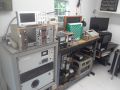
Well, it's been 5 years since I last posted in this thread, but the quad ion gun setup for the Mark 3 fusor is now operational. Pictures of the power supply and setup follow:
Ion injector operating in testbed
Ion injector operating in testbed
Control board, 4 adjustable buck converters for EMCO HV power supplies
EMCO HV power supplies (5kV, 3mA), box and front panel
Power supply assembled
MHV connections to the 4 anode layer ion sources on the fusor
Star mode with 4 injectors running at 700v anode bias
The supply will be further upgraded to have a fiber optic signal to allow the injectors to be pulsed. This is so a capacitor can be placed in parallel with the central grid and charged up while the fusor is pumped down below the minimum paschen breakdown pressure. The injectors can then be pulsed triggering the breakdown and generating a very high density plasma for a short period of time (for use with the laser density probe).
Ion injector operating in testbed
Andrew Seltzman
www.rtftechnologies.org
www.rtftechnologies.org
-
Richard Hull
- Moderator
- Posts: 15027
- Joined: Fri Jun 15, 2001 9:44 am
- Real name: Richard Hull
Re: Anode layer ion source. Operation pictures
Any fusion, neutron numers on this most interesting setup?
Richard Hull
Richard Hull
Progress may have been a good thing once, but it just went on too long. - Yogi Berra
Fusion is the energy of the future....and it always will be
The more complex the idea put forward by the poor amateur, the more likely it will never see embodiment
Fusion is the energy of the future....and it always will be
The more complex the idea put forward by the poor amateur, the more likely it will never see embodiment
-
Dennis P Brown
- Posts: 3189
- Joined: Sun May 20, 2012 10:46 am
- Real name: Dennis Brown
Re: Anode layer ion source. Operation pictures
Very professional setup - your design and execution appears to be working extremely well. Hope this provides far better fusion results!
-
Werner Engel

- Posts: 145
- Joined: Sun Aug 18, 2013 11:51 am
- Real name: Werner Engel
- Location: Vienna, Austria
- Contact:
Re: Anode layer ion source. Operation pictures
Hi Andrew!
Great that you still work on the fusor! Thanks for all your posts - great pictures and details!
What kind of "laser density probe" do you use in this case?
Interferometry, reflectometry, scattering, refractive index?
BR,
Werner
Great that you still work on the fusor! Thanks for all your posts - great pictures and details!
What kind of "laser density probe" do you use in this case?
Interferometry, reflectometry, scattering, refractive index?
BR,
Werner
-
Andrew Seltzman
- Posts: 810
- Joined: Sun Feb 01, 2004 8:02 pm
- Real name: Andrew Seltzman
- Contact:
Re: Anode layer ion source. Operation pictures
Hi Werner,
It's going to be a CO2 interferometer.
http://www.rtftechnologies.org/physics/ ... ometer.htm
Andrew
It's going to be a CO2 interferometer.
http://www.rtftechnologies.org/physics/ ... ometer.htm
Andrew
Andrew Seltzman
www.rtftechnologies.org
www.rtftechnologies.org
-
Werner Engel
- Posts: 145
- Joined: Sun Aug 18, 2013 11:51 am
- Real name: Werner Engel
- Location: Vienna, Austria
- Contact:
Re: Anode layer ion source. Operation pictures
Hi Andrew!
Congratulations to your final picture (the one showing the interference pattern)!
It's an enormous amount of work doing this @10,6µm with all the special materials. The carbon-pipe is it really stiff enough? What about vibrations from the roughing pump? Or did you switch off pumping during the measurement? Did you choose the 10,6 due to absorption of the plasma to be expected at that density (plasma frequency) or to reduce vibration induced problems?? Thomson Scattering is done @1064 nm (Nd:YAG) at the Tokamak in Garching. It seems they do not care about wavelength. But other refractive index measurements try to use as large as possible wavelengths.
I just built a “normal” HeNe-Michelson to get comfortable with optics. But this will be adapted in several steps.
Attached a Picture of my Michelson and one of the Nd:YAGs in Garching.
BR,
Werner
- Attachments
-
-
-
Andrew Seltzman
- Posts: 810
- Joined: Sun Feb 01, 2004 8:02 pm
- Real name: Andrew Seltzman
- Contact:
Re: Anode layer ion source. Operation pictures
New modifications to the anode layer ion source:
The old flat anode ring has been replaces with a conical anode ring (6.6 degree inward) for better beam focusing. this should have the focal point about 3" in front of the face of the source, right at the focal point of the fusor. In reality there still is the effect from space charge repelling the beam so it doesn't focus to a point, though the beam is considerably better defined with a tighter focus.
The NdFeB magnet has also been replaced with a SmCo magnet for higher temperature operation(up to 300C instead of 80C for the NdFeB)
Stainless Steel Belleville Disc Spring (mcmaster 9713K437) (6.6 degree inward angle) and jig to bore to correct ID
New and old anode rings
SmCo magnet installed
Modified injector re-assembled
Ion beam
Video of operation
https://www.youtube.com/watch?v=DbfmR5t ... e=youtu.be
https://www.youtube.com/watch?v=UDQ1BAH ... e=youtu.be
The old flat anode ring has been replaces with a conical anode ring (6.6 degree inward) for better beam focusing. this should have the focal point about 3" in front of the face of the source, right at the focal point of the fusor. In reality there still is the effect from space charge repelling the beam so it doesn't focus to a point, though the beam is considerably better defined with a tighter focus.
The NdFeB magnet has also been replaced with a SmCo magnet for higher temperature operation(up to 300C instead of 80C for the NdFeB)
Stainless Steel Belleville Disc Spring (mcmaster 9713K437) (6.6 degree inward angle) and jig to bore to correct ID
https://www.youtube.com/watch?v=DbfmR5t ... e=youtu.be
https://www.youtube.com/watch?v=UDQ1BAH ... e=youtu.be
Andrew Seltzman
www.rtftechnologies.org
www.rtftechnologies.org
-
Andrew Seltzman
- Posts: 810
- Joined: Sun Feb 01, 2004 8:02 pm
- Real name: Andrew Seltzman
- Contact:
Re: Anode layer ion source. Operation pictures
Additional pole pieces have been tested to determine the effect of the magnetic field position on beam focusing
Numbers 1,2,and 3 from left, pole piece 1 was the one used in all previous tests
The version 1 has a 1/8" step of 0.5" dia, then a 1/16" step of 0.625" dia, then a 45degree taper over 1/16"
The version 2 has a1/16" step of 0.5" dia, then a 1/16" step of 0.58" dia, then a 15degree taper over 1/16"
The version 3 has a 1/16" step of 0.5" dia, then a 15degree taper over 0.1875"
Version 2 pole piece and plasma focus
Version 2 pole piece recessed and plasma focus
Version 3 pole piece and plasma focus
Version 3 pole piece recessed and plasma focus
Numbers 1,2,and 3 from left, pole piece 1 was the one used in all previous tests
The version 1 has a 1/8" step of 0.5" dia, then a 1/16" step of 0.625" dia, then a 45degree taper over 1/16"
The version 2 has a1/16" step of 0.5" dia, then a 1/16" step of 0.58" dia, then a 15degree taper over 1/16"
The version 3 has a 1/16" step of 0.5" dia, then a 15degree taper over 0.1875"
Andrew Seltzman
www.rtftechnologies.org
www.rtftechnologies.org
-
Andrew Seltzman
- Posts: 810
- Joined: Sun Feb 01, 2004 8:02 pm
- Real name: Andrew Seltzman
- Contact:
Re: Anode layer ion source. Operation pictures
Further pole pieces tested
Numbers 1,2,and 3 from left, pole piece 1 was the one used in all previous tests
The version 1 has a 1/8" step of 0.5" dia, then a 1/16" step of 0.625" dia, then a 45degree taper over 1/16"
The version 2 has a 1/16" step of 0.5" dia, then a 1/16" step of 0.58" dia, then a 15degree taper over 1/16"
The version 3 has a 1/16" step of 0.5" dia, then a 15degree taper over 0.1875"
The version 4 is 7.5mm long 14mm dia
The version 5 has a 1/16" step of 0.5" dia, then a 1/16" step of 0.58" dia, then a 15degree taper over 1/8"
Version 4 and 5 have a pump out groove milled in the base to vent the trapped volume inside the magnet
Version 4 pole piece and plasma focus
Version 5 pole piece and plasma focus
Version 5 is going to be the final version used to upgrade the ion sources, it seems to hold the best focus
Numbers 1,2,and 3 from left, pole piece 1 was the one used in all previous tests
The version 1 has a 1/8" step of 0.5" dia, then a 1/16" step of 0.625" dia, then a 45degree taper over 1/16"
The version 2 has a 1/16" step of 0.5" dia, then a 1/16" step of 0.58" dia, then a 15degree taper over 1/16"
The version 3 has a 1/16" step of 0.5" dia, then a 15degree taper over 0.1875"
The version 4 is 7.5mm long 14mm dia
The version 5 has a 1/16" step of 0.5" dia, then a 1/16" step of 0.58" dia, then a 15degree taper over 1/8"
Version 4 and 5 have a pump out groove milled in the base to vent the trapped volume inside the magnet
Andrew Seltzman
www.rtftechnologies.org
www.rtftechnologies.org
-
Steven Sesselmann
- Posts: 2128
- Joined: Wed Aug 10, 2005 9:50 pm
- Real name: Steven Sesselmann
- Location: Sydney - Australia
- Contact:
Re: Anode layer ion source. Operation pictures
Andrew,
Once again I commend you on your engineering skills and systematic approach to solving a problem, this work on your anode layer source would be worth writing a paper on.
It will be interesting to see if the narrower beam increases the fusion rate or efficiency.
Steven
Once again I commend you on your engineering skills and systematic approach to solving a problem, this work on your anode layer source would be worth writing a paper on.
It will be interesting to see if the narrower beam increases the fusion rate or efficiency.
Steven
http://www.gammaspectacular.com - Gamma Spectrometry Systems
https://www.researchgate.net/profile/Steven_Sesselmann - Various papers and patents on RG
https://www.researchgate.net/profile/Steven_Sesselmann - Various papers and patents on RG
-
Andrew Seltzman
- Posts: 810
- Joined: Sun Feb 01, 2004 8:02 pm
- Real name: Andrew Seltzman
- Contact:
Re: Anode layer ion source. Operation pictures
Performance curves for the anode layer ion source
Andrew Seltzman
www.rtftechnologies.org
www.rtftechnologies.org
-
Andrew Seltzman
- Posts: 810
- Joined: Sun Feb 01, 2004 8:02 pm
- Real name: Andrew Seltzman
- Contact:
Re: Anode layer ion source. Operation pictures
I finally got around to converting all the drawing for the ion source from my old cad program (KeyCad, made in 1992) into a modern program (Autodesk Inventor) and made some 3D models:
Andrew Seltzman
www.rtftechnologies.org
www.rtftechnologies.org
-
Werner Engel
- Posts: 145
- Joined: Sun Aug 18, 2013 11:51 am
- Real name: Werner Engel
- Location: Vienna, Austria
- Contact:
Re: Anode layer ion source. Operation pictures
Did you allready try to focus the beam? Maybe with a Wehnelt cylinder or an einzellens?
Or is this even planned?
Higher luminosity would be nice - I think.
Or is this even planned?
Higher luminosity would be nice - I think.